


Intel
®
820E Chipset
R
150 Design Guide
3.2.5.2. Crosstalk Analysis
AGTL+ crosstalk simulations can consider as non-coupled the processor core package, the Intel 82820
MCH package, and the Intel PGA370 socket. Simulate the traces as lossless for worst-case crosstalk and
lossy where more accuracy is needed. Evaluate both odd-mode and even-mode crosstalk conditions.
AGTL+ crosstalk simulation involves the following cases:
• Intragroup AGTL+ crosstalk
• Intergroup AGTL+ crosstalk
• Non-AGTL+ to AGTL+ crosstalk
3.2.5.3. Monte Carlo Analysis
Perform a Monte Carlo Analysis on the extracted baseboard. Vary all parameters recommended for pre-
layout Monte Carlo Analysis within the regions in which they are expected to vary. The ranges for some
parameters will be reduced relative to those in the pre-layout simulations. For example, baseboard
lengths L1 through L7 should no longer vary across the full minimum and maximum ranges in the final
baseboard design. Instead, baseboard lengths should now have an actual route, with length tolerances
specified by the baseboard fabrication manufacturer.
3.2.6. Validation
Build systems and validate the design and simulation assumptions.
3.2.6.1. Measurements
Note that the AGTL+ specification for signal quality is at the component pad. The expected method of
signal quality determination is to run analog simulations for the pin and the pad. Then correlate the
simulations at the pin with actual system measurements at the pin. Good correlation at the pin leads to
confidence that the simulation at the pad is accurate. Controlling the temperature and voltage to
correspond with the I/O buffer model extremes should enhance the correlation between simulations and
the actual system.
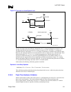
3.2.6.2. Flight Time Simulation
As defined in Section 3.1, flight time is the time difference between a signal crossing V
REF
at the input
pin of the receiver and the output pin of the driver crossing V
REF
, assuming it drives a test load. The
timings in the tables and topologies discussed in this guideline assume that the actual system load is 50
Ω
and is equal to the test load. Although the DC loading of the AGTL+ bus in a DP mode is closer to 25
Ω,
AC loading is approximately 29
Ω since the driver effectively “sees” a 56 Ω termination resistor in
parallel with a 60
Ω transmission line on the Intel PGA370 socket.