Intel
®
820E Chipset
R
154 Design Guide
Additional aggressors are possible in the z-direction, if adjacent signal layers are not routed in mutually
perpendicular directions. Because crosstalk coupling coefficients decrease rapidly with increasing
separation, it is rarely necessary to consider aggressors at least five line widths away from the victim.
The maximum crosstalk occurs when all aggressors are switching in the same direction at the same time.
The crosstalk that occurs internally in the IC packages also can affect the signal quality.
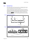
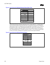
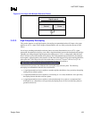
Backward crosstalk is present in both stripline and microstrip geometry’s (see Figure 78). Stripline
geometry differs from microstrip geometry in that the former requires stripping a layer away to see the
signal lines. The backward-coupled amplitude is proportional to the backward crosstalk coefficient, the
aggressor’s signal amplitude, and the coupled length of the network, up to a maximum that depends on
the rise/fall time of the aggressor’s signal. Backward crosstalk reaches a maximum (and remains
constant) when the propagation time on the coupled network length exceeds one-half of the rise time of
the aggressor’s signal. Assuming the ideal ramp on the aggressor to be from 0% to 100% voltage swing
and the fall time on an unloaded coupled network, then:
Length for max. backward crosstalk = (½
× fall time) / Board delay per unit length
The following example calculation results when the fast corner fall time is 3 V/ns and the board delay is
175 ps/inch (2.1 ns/foot):
Fall time = 1.5 V
/ 3 V/ns = 0.5 ns
Length for max. backward crosstalk = (½
× 0.5 ns × 1000 ps/ns) / 175 ps/in = 1.43 inches
Agents on the AGTL+ bus drive signals in each direction on the network. This causes backward crosstalk
from segments on two sides of a driver. The pulses from the backward crosstalk travel toward each other,
meet, and
add at certain moments and positions on the bus. This can double the voltage (i.e., noise) from
crosstalk.
3.3.3.1. Potential Termination Crosstalk Problems
It may not be suitable to utilize commonly used “pull-up” resistor networks for AGTL+ termination.
These networks have a common power or ground pin at the extreme end of the package, shared by 13 to
19 resistors (for 14-pin and 20-pin components). These packages generally have too much inductance to
maintain the voltage/current needed at each resistive load. Intel recommends using discrete resistors,
resistor networks with separate power/ground pins for each resistor, or working with a resistor network
vendor to obtain resistor networks that have acceptable characteristics.


