


Intel
®
820E Chipset
R
172 Design Guide
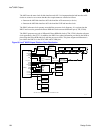
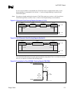
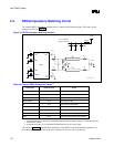
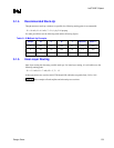
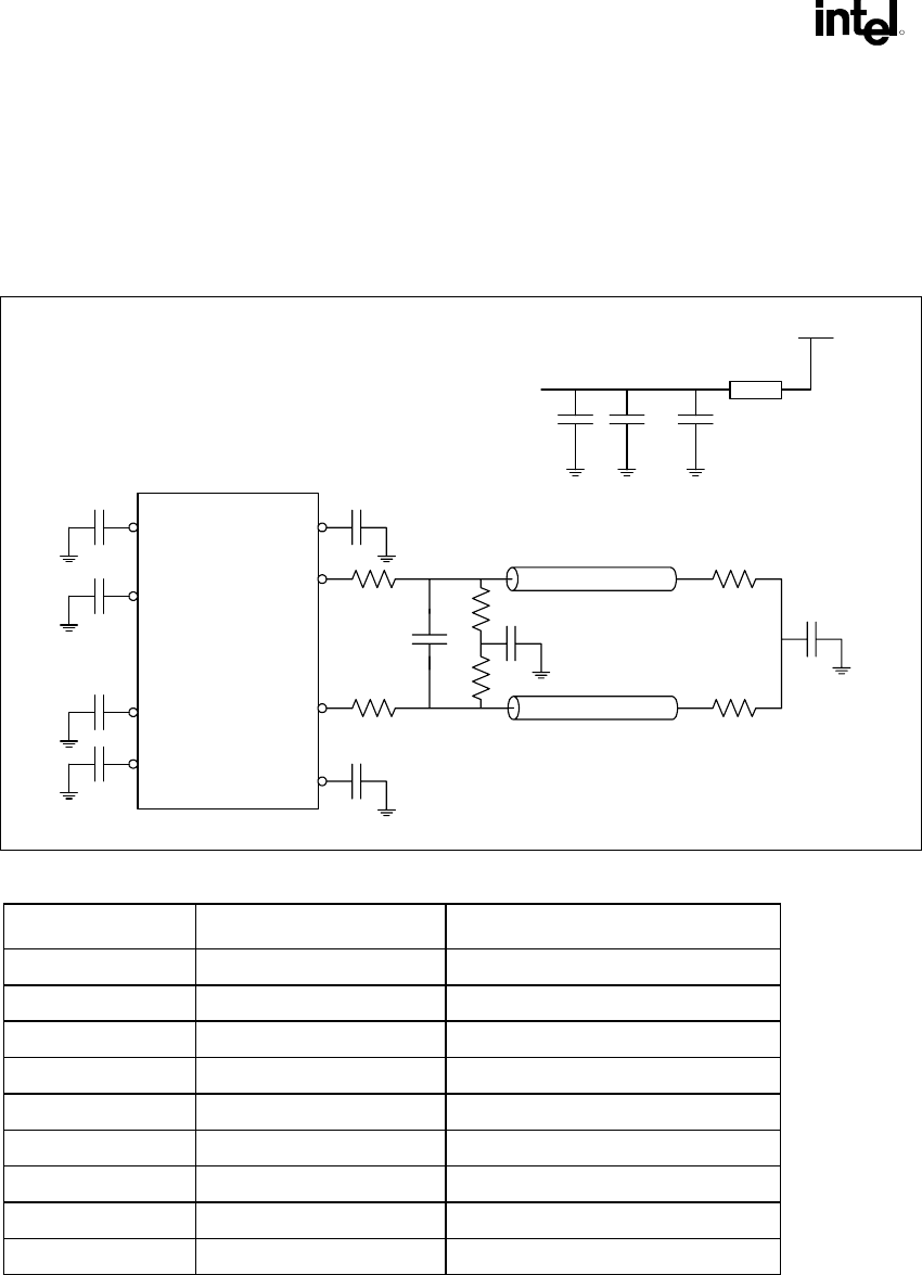
4.3. DRCG Impedance Matching Circuit
The external DRCG impedance matching circuit is shown in the following figure. The values for the
elements are listed in Table 59.
Figure 94. DRCG Impedance Matching Network
DRCG
C
D
R
S
R
P
R
T
Z
CH
C
F
V
DD
V
DD
O
V
DD
O
C
D
R
S
C
MID
R
P
Z
CH
C
MID2
R
T
IR
V
DD
P
V
DD
V
DD
C
IPD
C
D
C
D
C
D
C
D
3.3 V
FBead
CBulkCD2
CD2
To 3.3-V DRCG
supply connection
drcg_imped_match
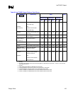
Table 59. External DRCG Component Values
1,2
Component Nominal Value Notes
CD 0.1 µF Decoupling caps to ground
RS 39 Ω Series termination resistor
RP 51 Ω Parallel termination resistor
CMID, CMID2 0.1 µF Virtual ground caps
RT 27 Ω End of channel termination
CF 4 pF Do not stuff
Fbead 50 Ω at 100 MHz Ferrite bead
CD2 0.1 µF Additional 3.3 V decoupling caps
Cbulk 10 µF Bulk cap on device side of ferrite bead
NOTES:
1. The ferrite bead and 10 µF bulk cap combination improves jitter and helps to keep the clock noise away from
the rest of the system.
2. For DRCG decoupling, 0.1 µF capacitors are better than 0.01 µF or 0.001 µF caps.
The circuit in Figure 94 must match the impedance of the DRCG to the 28 Ω channel impedance. For
more detailed information, refer to the
Direct Rambus Clock Generator Specification.