


Intel
®
820E Chipset
R
64 Design Guide
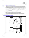
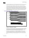
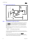
The strobe signals (AD_STB0, AD_STB0#, AD_STB1, AD_STB1#, SB_STB, and SB_STB#) act as
clocks on the source-synchronous AGP interface. Therefore, special care must be taken when routing
these signals. Because each strobe pair is truly a differential pair, the pair should be routed together. (For
example, AD_STB0 and AD_STB0# should be routed next to each other.) The two strobes in a strobe
pair should be routed on 5 mil traces with at least 20 mils of space (1:4) between them. This pair should
be separated from the rest of the AGP signals (and all other signals) by at least 20 mils (1:4). The strobe
pair must be length-matched to less than ±0.1 inch. (i.e., a strobe and its complement must be the same
length, within 0.1 inch.)
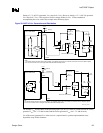
All AGP Interfaces
The 2×/4× timing domain signals can be routed with 5 mil spacing when breaking out of the MCH. The
routing must widen to the documented requirements within 0.3 inch of the MCH package.
When matching the trace length for the AGP 4× interface, all traces should be matched from the ball of
the MCH to the pin on the AGP connector. It is not necessary to compensate for the length of the AGP
signals on the MCH package.
Reduce line length mismatch to ensure added margin. To reduce trace-to-trace coupling (crosstalk),
separate the traces as much as possible. All signals in a signal group should be routed on the same layer.
The trace length and trace spacing requirements must not be violated by any signal. Trace length
mismatch for all signals within a signal group should be as close to zero as possible, to provide timing
margin.
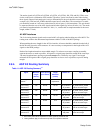
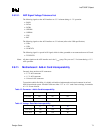
2.8.4. AGP 2.0 Routing Summary
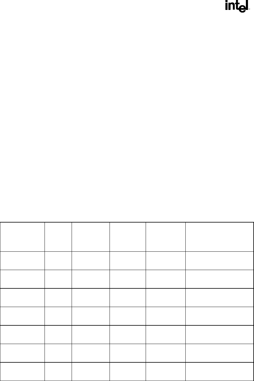
Table 11. AGP 2.0 Routing Summary
1,2
Signal Maximum
Length
(inches)
Trace Spacing
(5 mil Traces)
Length
Mismatch
(inches)
Relative To Notes
1× Timing
Domain
7.5 5 mils No
requirement
N/A None
2×/4× Timing
Domain Set 1
7.25 20 mils ±0.125 AD_STB0 and
AD_STB0#
AD_STB0 and AD_STB0#
must be the same length.
2×/4× Timing
Domain Set 2
7.25 20 mils ±0.125 AD_STB1 and
AD_STB1#
AD_STB1 and AD_STB1#
must be the same length.
2×/4× Timing
Domain Set 3
7.25 20 mils ±0.125 SB_STB and
SB_STB#
SB_STB and SB_STB# must
be the same length.
2×/4× Timing
Domain Set 1
6 15 mils
1
±0.5 AD_STB0 and
AD_STB0#
AD_STB0 and AD_STB0#
must be the same length.
2×/4× Timing
Domain Set 2
6 15 mils
1
±0.5 AD_STB1 and
AD_STB1#
AD_STB1 and AD_STB1#
must be the same length.
2×/4× Timing
Domain Set 3
6 15 mils
1
±0.5 SB_STB and
SB_STB#
SB_STB and SB_STB# must
be the same length.
NOTES:
1. Each strobe pair must be separated from other signals by at least 20 mils.
2. These guidelines apply to board stack-ups with 10% impedance tolerance.