


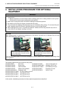
4. INSTALLATION PROCEDURE FOR OPTIONAL EQUIPMENT EO18-33027
4.1 DISC CUTTER (B-EX204-QM-R)
4- 2
4.1 DISC CUTTER (B-EX204-QM-R)
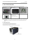
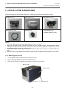
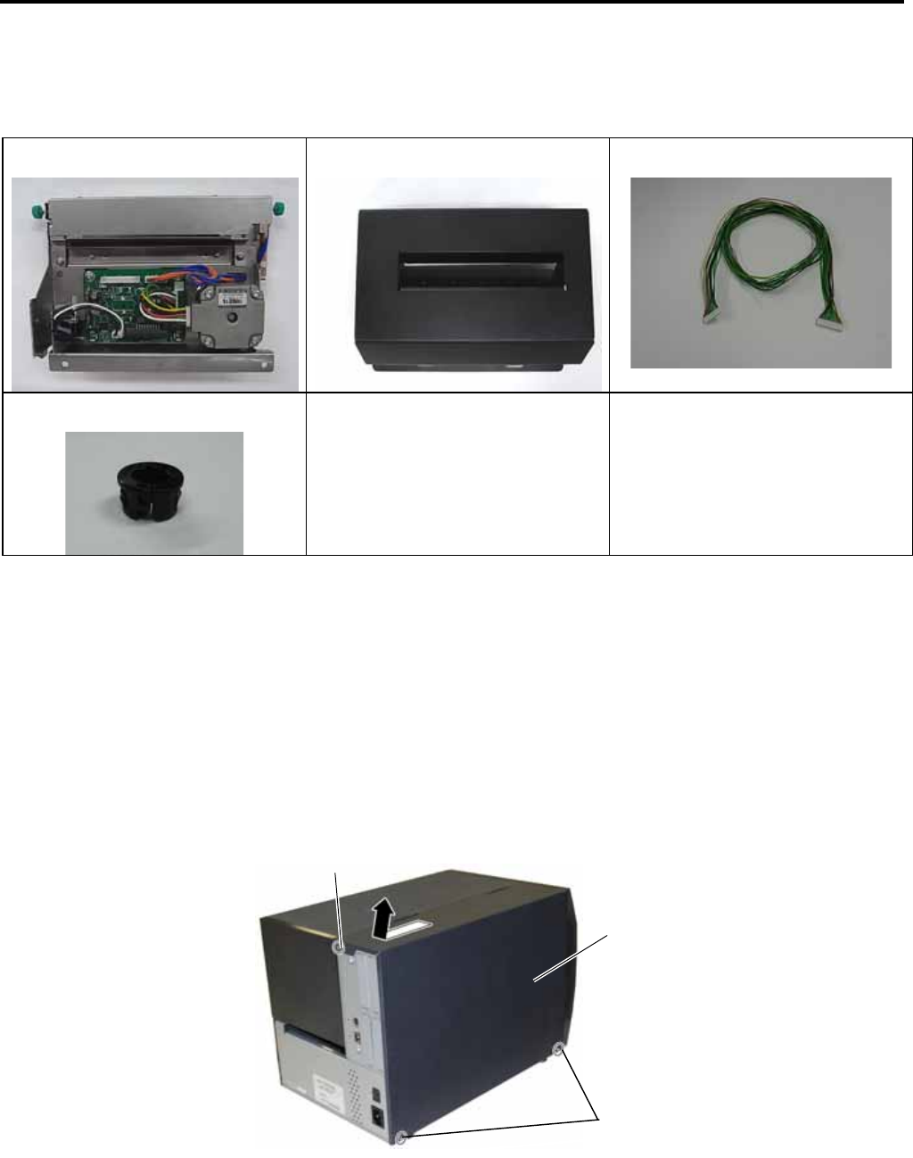
All the following parts are supplied with the kit. Make sure you have all items shown below.
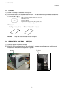
Cutter Unit (1 pc.)
Cutter Cover (1 pc.)
Harness Ass’y (1 pc.)
Cord bush (1 pc.)
• M-4x6 Screw (2 pcs.)
• FL-3x6 Screw (1 pc.)
• Installation Manual (1 copy)
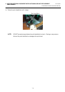
NOTE: This module cannot be used together with the B-EX904-H-QM-R peel-off module or B-EX204-R-QM-R
rotary cutter.
When this cutter is used together with an RFID module, be sure to install the RFID module prior to the
cutter.
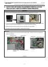
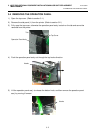
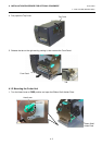
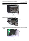
4.1.1 Removing the Covers
1. Turn the printer power off and disconnect the Power Cord.
2. Remove the three B-4x5 screws from the Side Panel (L).
3. Slide the Side Panel (L) backward, and raise it to remove from the printer.
B-4x5 Screw
Side Panel (L)
B-4x5 Screw