


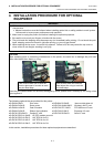
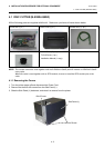
4. INSTALLATION PROCEDURE FOR OPTIONAL EQUIPMENT EO18-33027
4.1 DISC CUTTER (B-EX204-QM-R)
4- 6
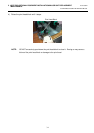
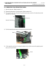
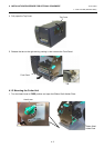
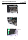
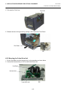
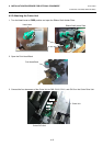
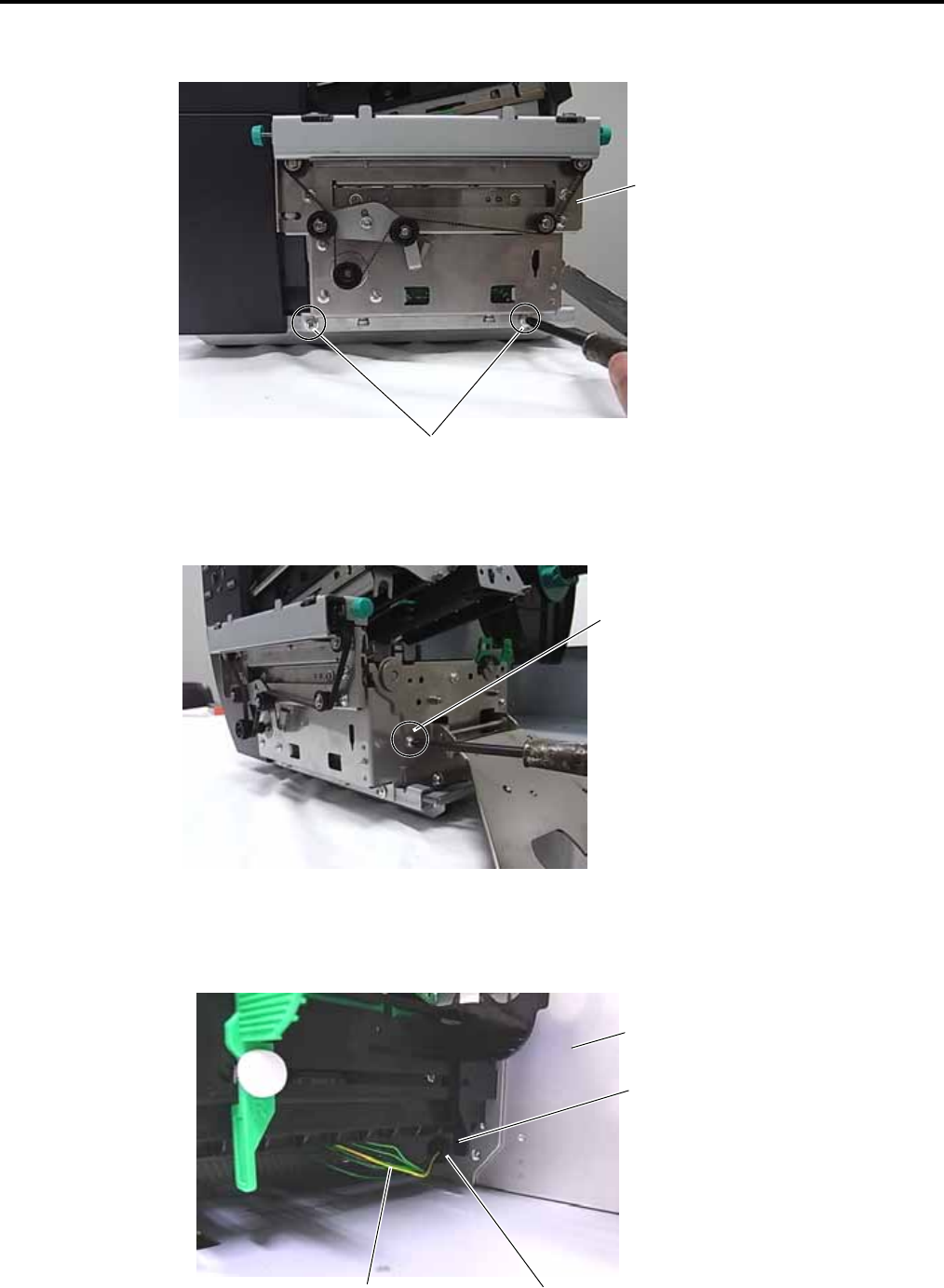
8. Secure the bottom of the Cutter Unit with the two M-4x6 screws.
9. Secure the side of the Cutter Unit with the FL-3x6 screw.
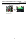
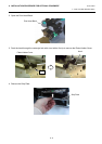
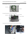
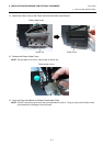
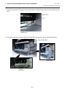
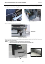
10. Insert the connector of the Harness Ass’y into the hole in the Main Frame, then fit the Cord Bush into
the hole.
M-4x6 Screw
Cutter Unit
FL-3x6 Screw
Hole
Main Frame
Harness Ass’y
Cord Bush