4. INSTALLATION PROCEDURE FOR OPTIONAL EQUIPMENT EO18-33027
4.2 ROTARY CUTTER (B-EX204-R-QM-R)
4-11
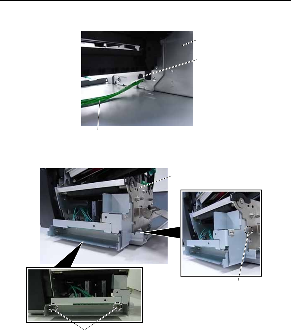
3. Insert the connector of the Harness Ass’y into the hole in the Main Frame, then fit the Cord Bush into the
hole.
4. Place the Cutter Drive Unit under the Platen Holder Block and secure it with the three M-4x8 screws.
Hole
Main Frame
Harness Ass’y
M-4x8 Screw
M-4x8 Screw
Platen Holder Block


