


4. INSTALLATION PROCEDURE FOR OPTIONAL EQUIPMENT EO18-33027
4.4 RIBBON SAVING MODULE (B-EX904-R-QM-R)
4-30
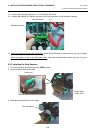
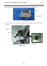
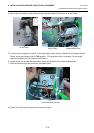
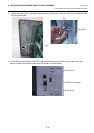
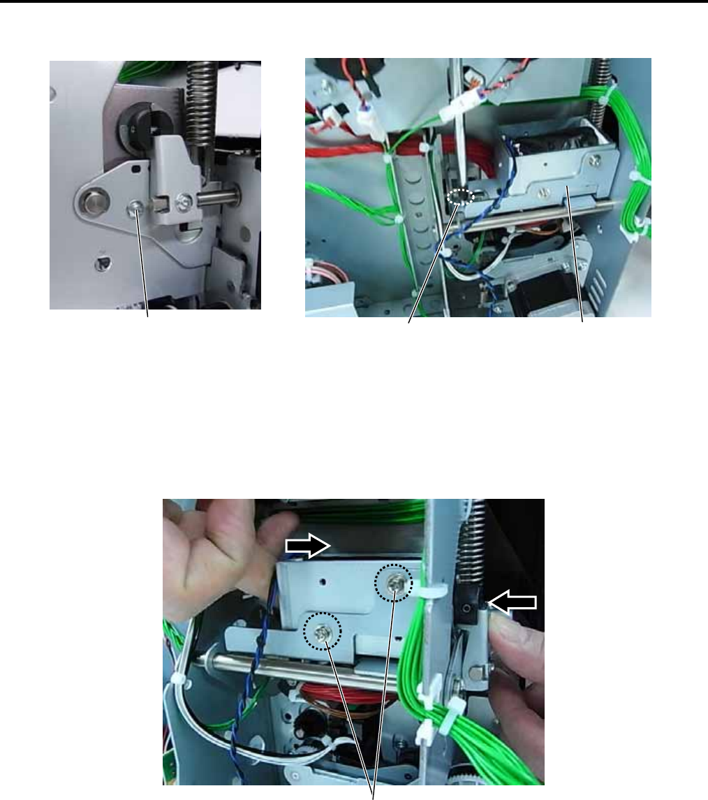
4. Secure the two portions of the Solenoid Base Plate with the M-3x6 Screws, as shown below.
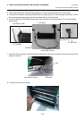
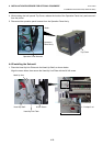
5. Fold (or stack) tag paper to make a 1.5-mm thick paper stack, insert it between the Print Head and the
Platen, and turn the Head Lever to TAG position. (The purpose of this is to make a 1.5 mm height
clearance between the Print Head and the Platen.)
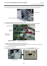
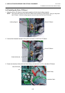
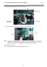
6. Loosen the M-3x6 screws that temporarily secure the Solenoid to the Solenoid Base Plate.
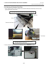
7. Push the Solenoid from the both sides, as shown below.
8. Tighten the M-3x6 screws loosened in the previous step.
Loosen the M-3x6 screws.
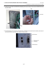
M-3x6 screw
M-3x6 screw
Solenoid Base Plate