


4. INSTALLATION PROCEDURE FOR OPTIONAL EQUIPMENT EO18-33027
4.4 RIBBON SAVING MODULE (B-EX904-R-QM-R)
4-29
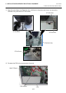
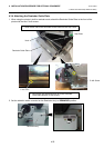
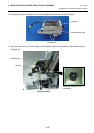
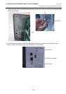
2. Temporarily secure the Solenoid to the Solenoid Base Plate with the two M-3x6 Screws.
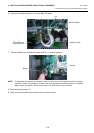
3. Insert the Head Up Arm into the Plunger of the Solenoid, and fit the protrusion of the Solenoid into the
“H-shape” cut.
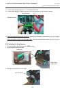
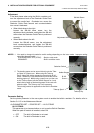
Head Up Arm
Plunger
Place the Solenoid in this
orientation.
M-3x6 screw
Solenoid Base Plate
Solenoid
View from above