4. INSTALLATION PROCEDURE FOR OPTIONAL EQUIPMENT EO18-33027
4.2 ROTARY CUTTER (B-EX204-R-QM-R)
4-12
4.2.3 Attaching the Cutter Unit
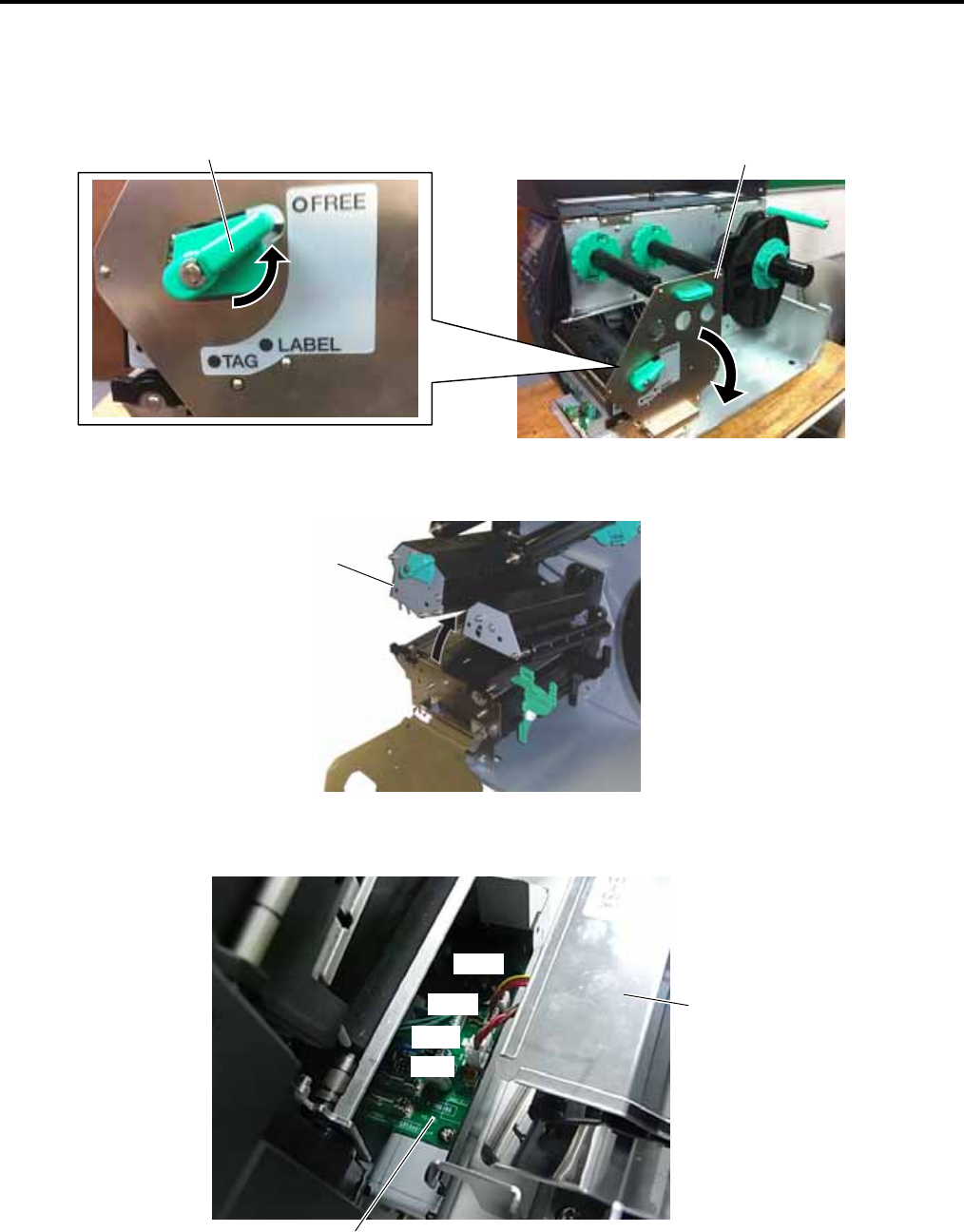
1. Turn the Head Lever to FREE position and open the Ribbon Shaft Holder Plate.
2. Open the Print Head Block.
3. Connect the four harnesses of the Cutter Unit to CN8, CN10, CN11, and CN12 on the Cutter Drive Unit.
Cutter Unit
Cutter Drive Unit
CN8
CN12
CN10
Print Head Block
Ribbon Shaft Holder Plate
Head Leve
r
CN11


