


4. INSTALLATION PROCEDURE FOR OPTIONAL EQUIPMENT EO18-33027
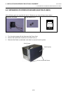
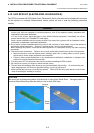
4.8 Parallel Interface Board (B-EX700-CEN-QM-R)
4-44
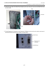
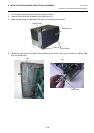
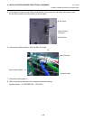
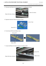
5. Fit the parallel interface connector of the parallel interface board into the slot from the inside, and secure
it with the two M-3x6 screws from the outside, as shown below.
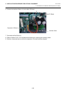
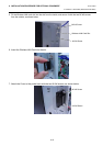
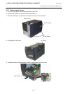
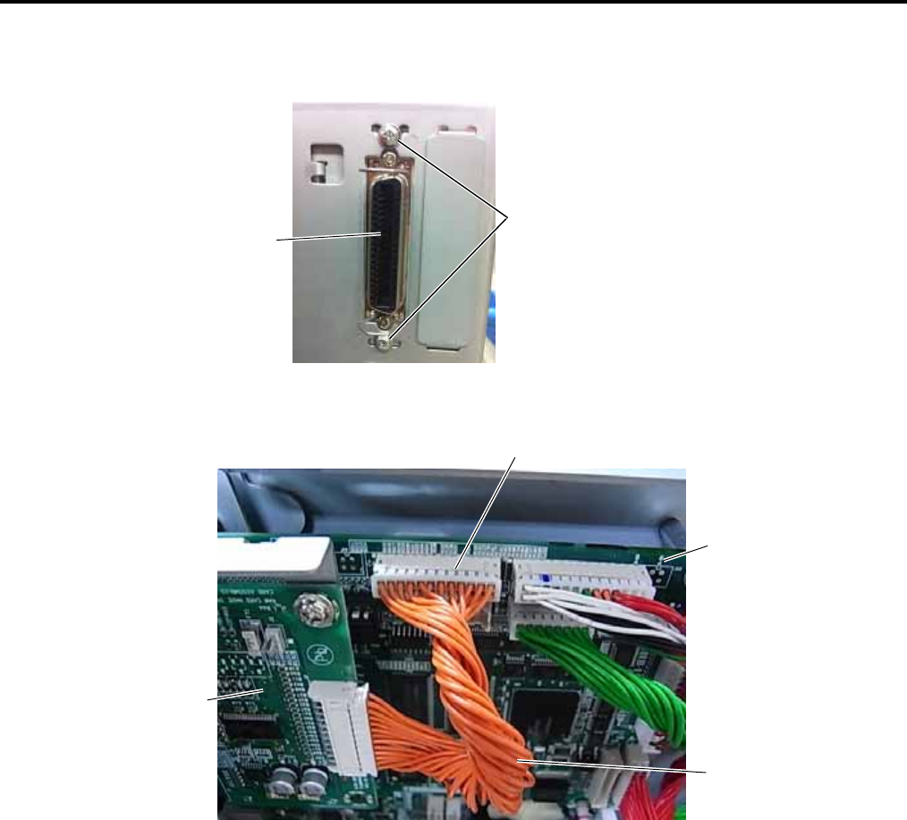
6. Connect the interface cable to J2 on the Main PC board.
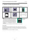
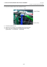
7. Re-install the Side panel (L).
8. Refer to the Owner’s Manual for the interface parameter settings.
(System Mode → <7>INTERFACE → CENTRO.)
M-3x 6 Screw
Parallel Interface
Connector
Main PC Board
J2
Interface Cable
Parallel Interface Board