


4. INSTALLATION PROCEDURE FOR OPTIONAL EQUIPMENT EO18-33027
4.11 HF RFID MODULE MOUNT KIT (B-EX700-RFID-H1-QM-R)
4-62
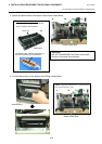
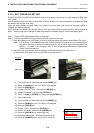
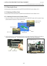
4.11.1 Removing the Covers
As the procedure is the same as that for the B-EX700-U2-US/EU/CN-R, refer to Section 4.10.1.
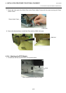
4.11.2 Attaching the Ribbon Guide
As the procedure is the same as that for the B-EX700-U2-US/EU/CN-R, refer to Section 4.10.2.
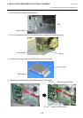
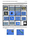
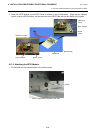
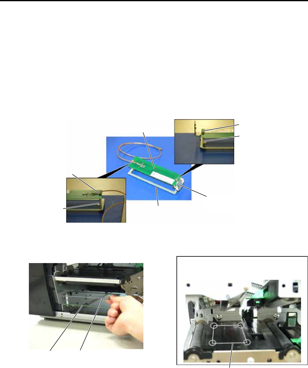
4.11.3 Attaching the Antenna to the Antenna Frame
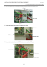
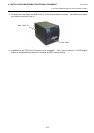
1. Secure the Antenna to the Antenna Frame with the two SMW-3x25 screws with the spacers (long)
placed between the Antenna and the Antenna Frame.
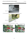
2. Hold the Antenna Ass’y so that the Antenna Frame is on the upper side and the Plate A is on the right, as
viewed from the printer front. Fit the Antenna Ass’y to the bottom of the Platen Holder Block. .
SMW-3x25 Screw
Antenna Frame
Antenna
Spacer (long)
Plate A
SMW-3x25 Screw
Spacer (long)
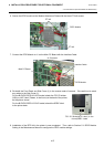
NOTE: Align the Antenna Ass’y with the four
slots enclosed with circles.
Antenna
Antenna Frame
Platen Holder Block