4. INSTALLATION PROCEDURE FOR OPTIONAL EQUIPMENT EO18-33027
4.2 ROTARY CUTTER (B-EX204-R-QM-R)
4-13
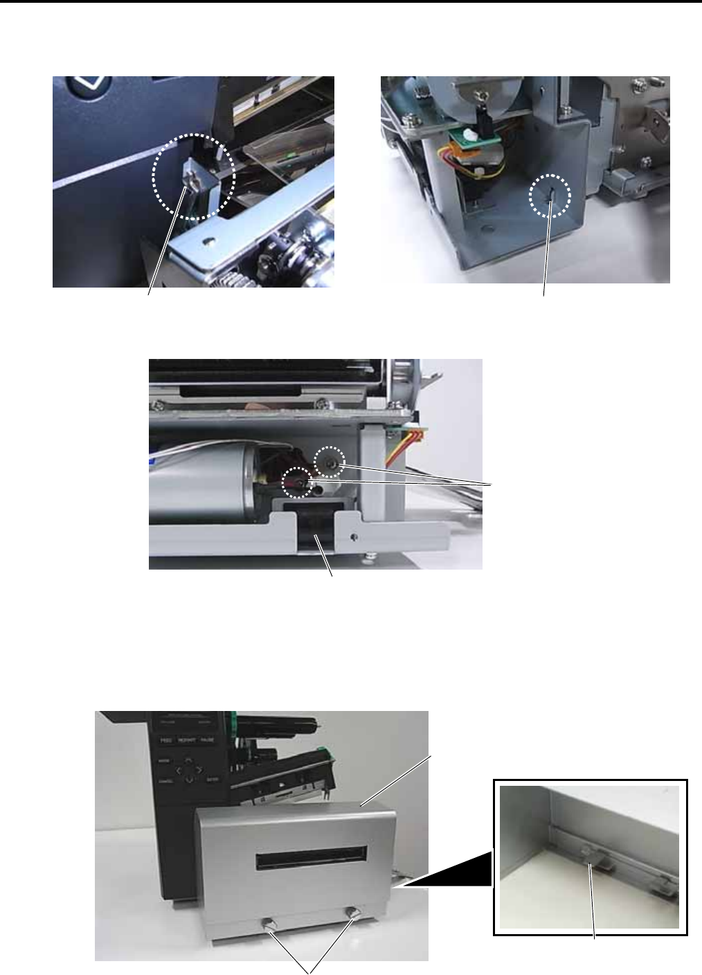
4. Place the hook at the left side of the Cutter Unit on the cut in the printer main frame. Fit the tab of the
Cutter Drive Unit into the slit in the Cutter Unit.
5. Secure the Cutter Unit with the M-4x8 screws.
6. Attach the Cutter Cover to the Cutter Unit with the two screws so that the tab of the Cutter Cover turns
on the Cutter Cover Open Switch.
NOTES: 1. Be careful not to pinch the cutter harness by the cutter cover.
2. Make sure that the anti-static brush is protruding from the media outlet.
Cutter Cover
Fit the tab into the slit.
Place the hook on the cut.
M-4x8 Screw
Cutter Cover Open Switch
Tab
Screw


