


4. INSTALLATION PROCEDURE FOR OPTIONAL EQUIPMENT EO18-33027
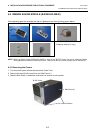
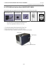
4.4 RIBBON SAVING MODULE (B-EX904-R-QM-R)
4-28
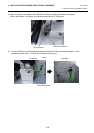
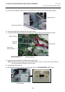
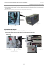
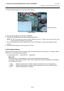
4. While holding the half opened Top Cover, release the hooks of the Operation Panel Ass’y and remove it
from the printer.
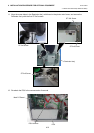
5. Disconnect the operation panel harness from the Operation Panel Ass’y.
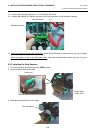
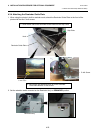
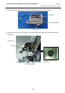
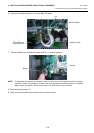
4.4.2 Installing the Solenoid
1. Place the Head Up Link Plate onto the Head Up Shaft, as shown below.
Align the screw holes, then secure the Head Up Link Plate with the M-3x6 screw.
Operation
Panel Ass’y
Hook
Operation Panel Harness
Top Cover
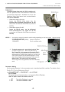
Head Up Shaft
M-3x6 Screw
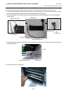
Head Up Link Plate
Head Up Arm
“H-shape” cut