


4. INSTALLATION PROCEDURE FOR OPTIONAL EQUIPMENT EO18-33027
4.4 RIBBON SAVING MODULE (B-EX904-R-QM-R)
4-27
4.4 RIBBON SAVING MODULE (B-EX904-R-QM-R)
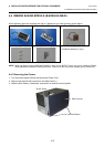
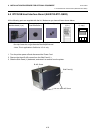
All the following parts are supplied with the kit. Make sure you have all items shown below.
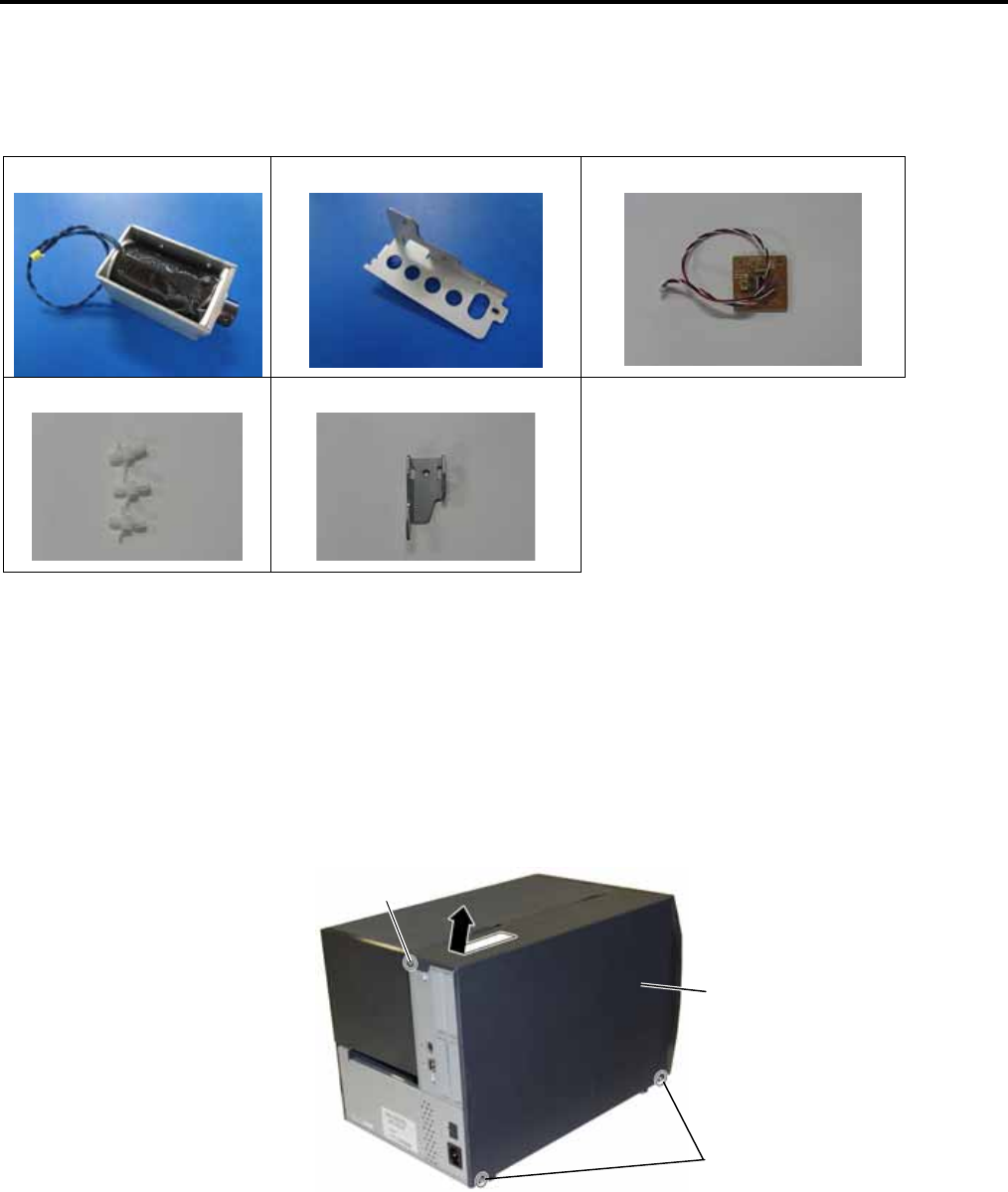
Solenoid (1 pc.)
Solenoid Base Plate (1 pc.)
Driver PC Board (1 pc.)
Locking Support (3 pcs.)
Head Up Link Plate (1 pc.)
• M3x6 Screw (5 pcs.)
• Installation Manual (1 copy)
NOTE: When the Rotary Cutter (B-EX204-R-QM-R) is used on the B-EX4T series, be sure to install the Ribbon
Saving Module to enable the head-up function. Failure to do this may cause a paper jam or ribbon error.
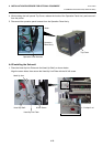
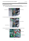
4.4.1 Removing the Covers
1. Turn the printer power off and disconnect the Power Cord.
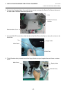
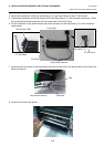
2. Remove the three B-4x5 screws from the Side Panel (L).
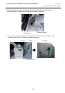
3. Slide the Side Panel (L) backward, and raise it to remove from the printer.
Side Panel (L)
B-4x5 Screw
B-4x5 Screw