4. INSTALLATION PROCEDURE FOR OPTIONAL EQUIPMENT EO18-33027
4.6 EXPANSION I/O INTERFACE BOARD (B-EX700-IO-QM-R)
4-37
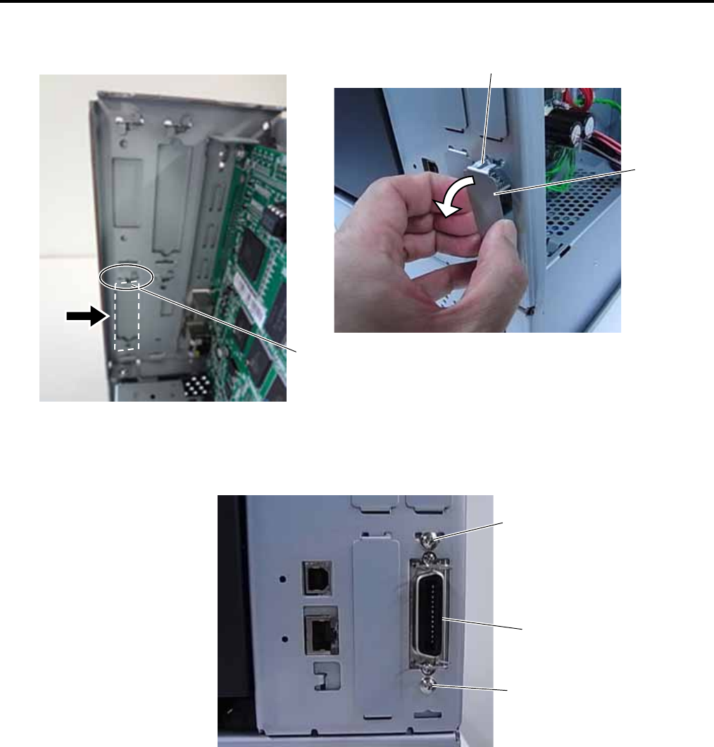
4. Unfold the upper tabs of the Blind Plate indicated by the arrow, then pull and remove the Blind Plate from
the printer back.
5. Fit the Expansion I/O Connector of the Expansion I/O Board into the slot from the inside, and secure it
with the two M-3x6 screws from the outside, as shown below.
Blind Plate
Tab
Tab
Expansion I/O
Connector
M-3x6 Screw
M-3x6 Screw


