4. INSTALLATION PROCEDURE FOR OPTIONAL EQUIPMENT EO18-33027
4.5 RTC/USB Host Interface Board (B-EX700-RTC-QM-R)
4-33
4.5 RTC/USB Host Interface Board (B-EX700-RTC-QM-R)
All the following parts are supplied with the kit. Make sure you have all items shown below.
RTC/USB host
interface board (1 pc.)
Battery (1 pc.)
(See Note below.)
M-3x6 Screw (2 pcs.)
Battery Label
(1 pc.)
Installation Manual
(1 copy)
NOTE: Perchlorate Material - special handling may apply.
See http://www.dtsc.ca.gov/hazardouswaste/perchlorate/
--Note; This is applicable to California, U.S.A. only.
1. Turn the printer power off and disconnect the Power Cord.
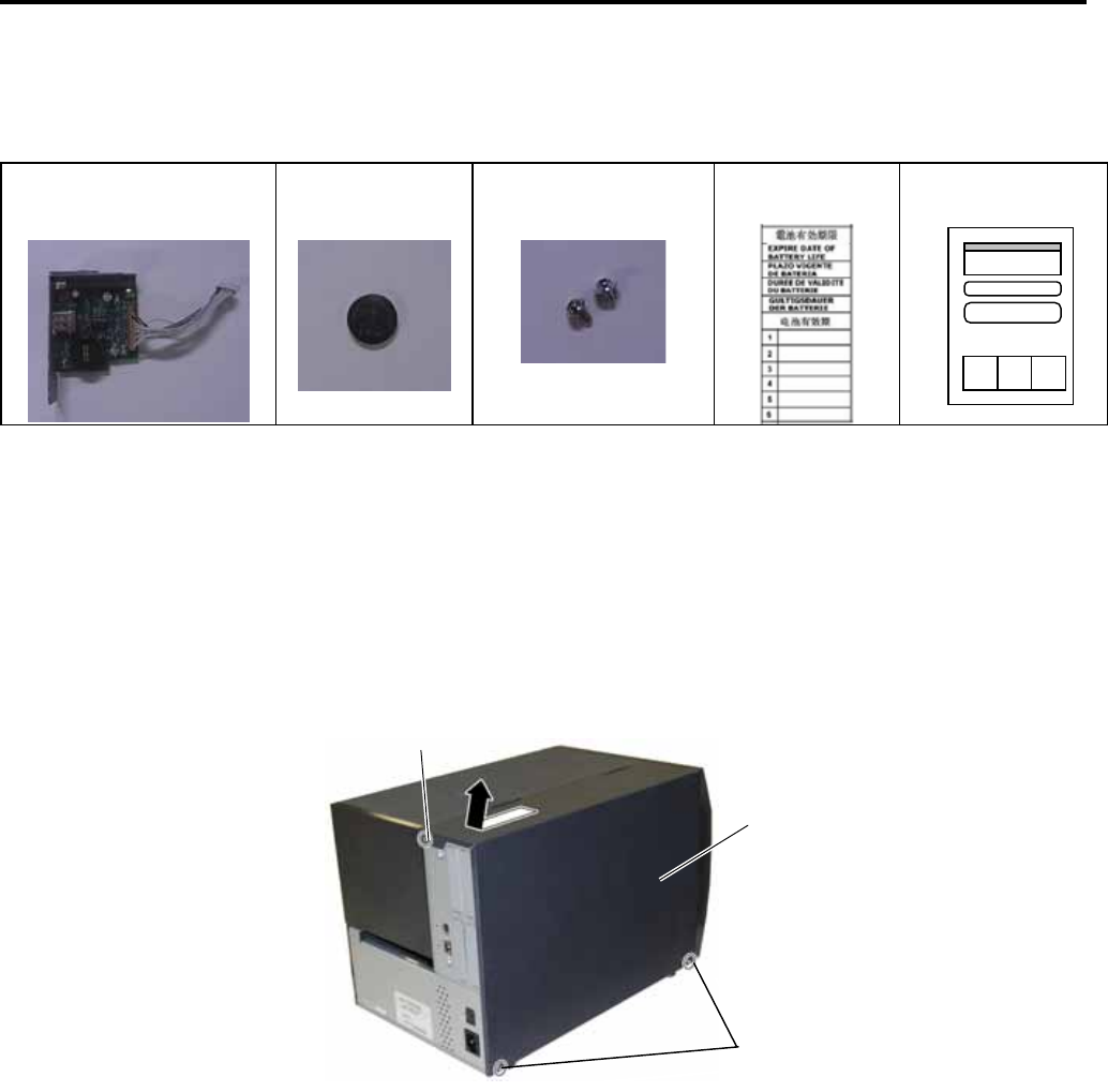
2. Remove the three B-4x5 screws from the Side Panel (L).
3. Slide the Side Panel (L) backward, and raise it to remove from the printer.
B-4x5 Screw
Side Panel (L)
B-4x5 Screw


