


24 AMD Geode™ LX Processors Data Book
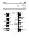
Signal Definitions
33234H
3.2 Bootstrap Options
The bootstrap options shown in Table 3-3 are supported in
the AMD Geode LX processor for configuring the system.
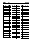
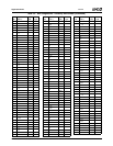
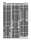
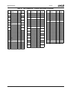
3.3 Ball Assignments
The tables in this chapter use several common abbrevia-
tions. Table 3-4 lists the mnemonics and their meanings.
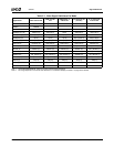
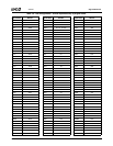
Table 3-3. Bootstrap Options
Pins Description
IRQ13 0: Normal boot operation, TAP reset
active during PCI reset
1: Debug stall of CPU after CPU
reset, TAP reset active until V
IO
valid
PW1 0: PCI (SYSREF) is 33 MHz
1: PCI (SYSREF) is 66 MHz
PW0,
SUSPA#,
GNT[2:0]#
Select CPU and GeodeLink system
MHz options including a PLL bypass
option. Refer to Table 6-87 on page
556 for programming.
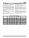
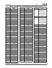
Table 3-4. Ball Type Definitions
Mnemonic Definition
AAnalog
I Input ball
I/O Bidirectional ball
CAV
SS
Core PLL Ground ball: Analog
CAV
DD
Core PLL Power ball: Analog
DAV
SS
DAC PLL Ground ball: Analog
DAV
DD
DAC PLL Power ball: Analog
MAV
SS
GLIU PLL Ground ball: Analog
MAV
DD
GLIU PLL Power ball: Analog
O Output ball
VAV
SS
Video PLL Ground ball: Analog
VAV
DD
Video PLL Power ball: Analog
V
CORE
Power ball: 1.2V (Nominal)
V
IO
I/O Power ball: 3.3V (Nominal)
V
MEM
Power ball: 2.5V
V
SS
Ground ball
# The “#” symbol at the end of a signal
name indicates that the active, or
asserted state, occurs when the sig-
nal is at a low voltage level. When “#”
is not present after the signal name,
the signal is asserted when at a high
voltage level.