


460 AMD Geode™ LX Processors Data Book
Video Processor Register Descriptions
33234H
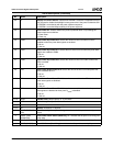
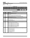
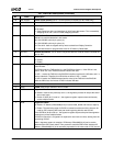
18 INV VS POL Invert VSYNC Polarity. Set to 1 to invert polarity of VSYNC (for 601 mode only).
17 INV HS POL Invert HSYNC Polarity. Set to 1 to invert polarity of HSYNC (for 601 mode only).
16 UV SWAP UV Swap.
0: No swap.
1: Swap lowest byte with next lowest byte in [23:0] input data stream. This is essentially
swapping the U and V, and if in RGB, swapping G and B.
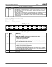
15:14 VSYNC SHFT VSYNC Shift. This is the number of VOP clocks to shift the VSYNC with respect to
HSYNC for odd field detection in 601 mode.
00: Shift VSYNC earlier by 4 cycles (-4).
01: Shift VSYNC earlier by 2 cycles (-2).
10: Zero shift - both are aligned as they were received from Display Controller.
11: Shift later based on programmable value in DC Memory Offset 080h.
13 DIS DEC Disable Decimation. This is used in conjunction with 601 mode for 24-bit YUV/RGB out-
put on VOP.
12 601 MODE Enable 601 Mode.
0: Disable.
1: Enable.
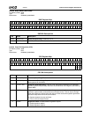
11 VBI Vertical Blanking Interval. When this bit is set to 1, the Task bit (bit 9) is used to indi-
cate VBI data.
In BT.656 mode, the TASK bit (bit 9) in the EAV/SAV is fixed at 1, if this VBI bit is set,
then a value of 0 in the TASK bit location indicates VBI data.
In VIP 1.1 mode, the TASK bit in the EAV/SAV is defined such that 0 is VBI data, and 1 is
active video data. Therefore, this VBI bit has no effect in VIP 1.1 mode.
In VIP 2.0 mode, the TASK bit determines the value of the TASK bit in the EAV/SAV.
With the VBI bit set, the inverse of TASK indicates VBI data.
10 RSVD Reserved. Reads back as 0.
9 TASK TASK. Value for the Task bit in VIP 2.0 mode.
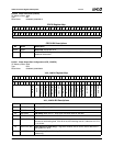
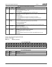
8SGFR Signature Free Run.
0: Disable. If this bit was previously set to 1, the signature process will stop at the end of
the current frame.
1: Enable. If SIGE (bit 7) is set to 1, the signature register captures data continuously
across multiple frames.
7SIGE Signature Enable.
0: Disable. VP Memory Offset 808h[31:0] is reset to 0000_0000h and held (no capture).
1: Enable. The next falling edge of VSYNC is counted as at the start of the frame to be
used for CRC checking with each pixel clock beginning with the next VSYNC.
If the SGFR bit (bit 8) is set to 1, the signature register captures the pixel data signature
continuously across multiple frames.
If SGFR is cleared to 0, a signature is captured for one frame at a time, starting from the
next falling VSYNC.
After a signature capture is complete, VP Memory Offset 808h[31:0] can be read to
determine the CRC check status. Then proceed to reset the SIGE which initializes VP
Memory Offset 808h[31:0] as an essential preparation for the next round of CRC checks.
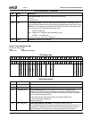
VOP_CONFIG
Bit Descriptions (Continued)
Bit Name Description