


AMD Geode™ LX Processors Data Book 391
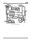
Video Processor
33234H
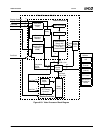
6.7.2.1 Video Formatter
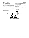
The Video Processor module accepts video data at a rate
asynchronous to the GLIU clock rate. The byte order of
video input data can be configured using the VID_FMT bits
in the Video Configuration register (VP Memory Offset
000h[3:2]).
Video input data can be in YUV 4:2:2, YUV 4:2:0, or RGB
5:6:5 format. The video input data is packed into a 32-bit
WORD and written to one of three on-chip line buffers to
significantly reduce video bandwidth. Each line buffer is
480x64 bits, and supports up to a maximum of 1920 hori-
zontal source video pixels.
YUV Video Formats
Two different input data formats can be used by the video
formatter for overlay of video or graphics data:
1) 4:2:2 Video Format
Four different types of 4:2:2 formats may be used. See
the VID_FMT bits in the Video Configuration register
(VP Memory Offset 000h[3:2]) for details about these
formats. Ensure that the selected format is appropriate
for the data source.
2) 4:2:0 Video Format
This format contains all Y data for each line followed
by all U data and all V data. For example, for a line
with 720 pixels, 720 bytes of Y data is followed by 360
bytes of U data and 360 bytes of V data for that line.
This format is usually used for input from the proces-
sor video buffer (i.e., generated by application soft-
ware).
This format is selected when the EN_420 bit (VP
Memory Offset 000h[28]) is set to 1. The following
possible subformat types (described for four bytes of
data) can be selected via the VID_FMT bits (VP Mem-
ory Offset 000h[3:2]):
00: Y0 Y1 Y2 Y3
01: Y3 Y2 Y1 Y0
10: Y1 Y0 Y3 Y2
11: Y1 Y2 Y3 Y0
Note: The above formats describe Y data. U and V
data have the same format (where “U” and “V” replace
the “Y” in this sample).
RGB Video Format
In this format, each pixel is described by 16 bits:
Bits [15:11]: Red
Bits [10:5]: Green
Bits [4:0]: Blue
This format can be used for a second graphics plane if
video mixing is not used.
Four subformats can be selected via the VID_FMT bits (VP
Memory Offset 000h[3:2]):
00: P1L P1M P2L P2M
01: P2M P2L P1M P1L
10: P1M P1L P2M P2L
11: P1M P2L P2M P1L
Notes:
1) P1M is the most significant byte (MSB) of pixel 1.
2) P1L is the least significant byte (LSB) of pixel 1.
3) P2M is the MSB of pixel 2.
4) P2L is the LSB of pixel 2.
5) Within each pixel (2 bytes) RGB ordering is constant.
6) This mode does not work if EN_420 is high (VP Mem-
ory Offset 000h[28] = 1).
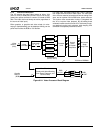
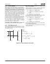
6.7.2.2 4x4 Filter/Scaler
• Accepts all SD and HD television resolutions as well as
non-standard video window sizes.
• Horizontal arbitrary scaling:
— Up to 1:8 upscale.
— Down to 8:1 downscale.
• Vertical arbitrary scaling:
— Up to 1:8 upscale.
— Down to 2:1 downscale.
• 16-pixel filtering:
— One horizontal 4-tap filter.
— Four parallel vertical 4-tap filters.
— 128 or 256 phase in both horizontal and vertical
directions.
— Programmable 16-bit signed horizontal and vertical
coefficients.
• Five video line buffers:
— Four active line buffers.
— One extra line buffer for buffer elasticity and down-
scale.
• Line buffer interface operates at GLIU clock up to 400
MHz.
• Horizontal and vertical filter/scaler operates at Dot clock
up to 350 MHz
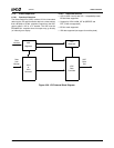
The VP 4x4 filter/scaler contains multiple 4-tap filters that
are used in conjunction with an upscale/downscale pro-
cessing section. There are five video line buffers that store
YUV pixels for upcoming display lines.