


612 AMD Geode™ LX Processors Data Book
Electrical Specifications
33234H
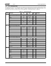
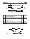
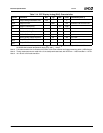
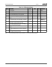
Table 7-12. CRT Interface Signals
Symbol Parameter Min Max Unit Comments
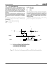
t
CK
DOTCLK Period 2.8 ns 350 MHz
t
CH
DOTCLK High time 1.2 ns 45% t
CK
t
CL
DOTCLK Low time 1.2 ns 45% t
CK
DOTCLK long term output jitter 15% t
CK
Note 1
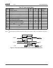
t
SKEW
Skew between RED, GREEN, BLUE Output Valid 0 0.6 ns Between any
two signals
Note 2
Note 1. Measured as per VESA requirements. The jitter is observed at its worst case point on a scan line after HSYNC
triggers up to and including the next HSYNC trigger.
Note 2. HSYNC and VSYNC for CRT timing are generated from the same on-chip clock that is used to generate the RED,
GREEN, and BLUE signals.
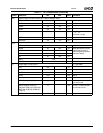
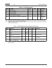
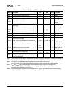
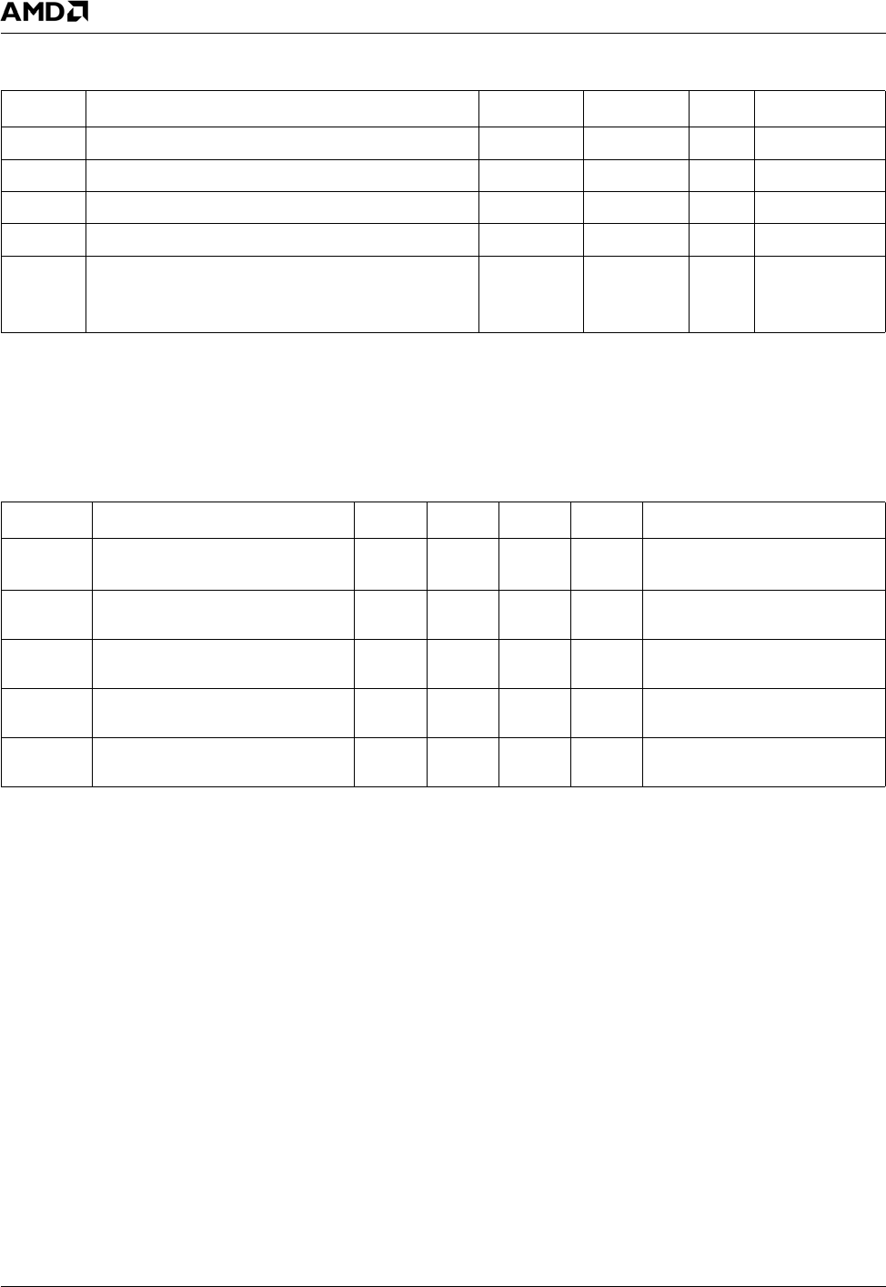
Table 7-13. CRT Display Recommended Operating Conditions
Symbol Parameter Min Typ Max Units Comments
V
DAC
Power Supply connected to
DAV
DD
3.14 3.3 3.46 V
R
L
Output Load RED, GREEN and
BLUE
37.5
Note 1
Ω One each signal.
I
OUT
Output Current RED, GREEN
and BLUE
21 mA One each signal.
R
SET
Value of the full-scale adjust
resistor connected to DRSET
1.2K Ω This resistor should have a
1% tolerance.
VEXT
REF
External voltage reference con-
nected to the DVREF pin
1.235 V
Note 1. There is a 75 Ω resistor on the motherboard and a 75 Ω resistor in the CRT monitor to create the effective 37.5 Ω
typical resistance.