


AMD Geode™ LX Processors Data Book 607
Electrical Specifications
33234H
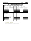
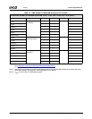
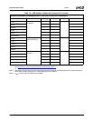
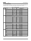
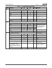
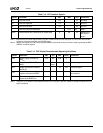
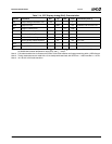
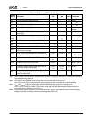
7.6 AC Characteristics
The following tables list the AC characteristics including
output delays, input setup requirements, input hold require-
ments, and output float delays. The rising-clock-edge refer-
ence level V
REF
, and other reference levels are shown in
Figure 7-2. Input or output signals must cross these levels dur-
ing testing.
Input setup and hold times are specified minimums that
define the smallest acceptable sampling window for which
a synchronous input signal must be stable for correct opera-
tion.
All AC tests are performed at the following parameters
using the timing diagram shown in Figure 7-2 unless other-
wise specified:
V
CORE
: 1.14V to 1.26V (1.2V Nominal)
V
IO
: 3.14V to 3.46V (3.3V Nominal)
V
MEM:
2.5V SSTL
MVREF: DDR:1.25V
T
C
:0
o
C to 85
o
C
R
L
:50 Ω
C
L
:50 pF
While most minimum, maximum, and typical AC character-
istics are only shown as a single value, they are tested and
guaranteed across the entire processor core voltage range
of 1.14V to 1.26V. AC characteristics that are affected sig-
nificantly by the core voltage or speed grade are docu-
mented accordingly.
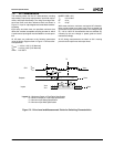
All AC timing measurements are taken at 50% crossing
points for both input times and output times.
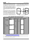
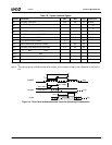
Figure 7-2. Drive Level and Measurement Points for Switching Characteristics
CLK
Outputs
Inputs
V
IHD
V
ILD
V
REF
Valid Input
Valid Output
n+1
Valid Output
n
V
REF
V
REF
V
ILD
V
IHD
Min
Max
Legend: A = Maximum Output or Float Delay Specification
B = Minimum Output or Float Delay Specification
C = Minimum Input Setup Specification
D = Minimum Input Hold Specification
T
X
B
A
CD