424 AMD Geode™ LX Processors Data Book
Video Processor Register Descriptions
33234H
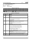
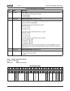
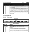
6.8.3.3 Video X Position (VX)
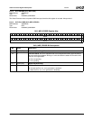
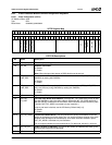
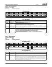
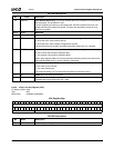
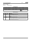
2 VSYNC_EN CRT Vertical Sync Enable. Enables/disables CRT vertical sync (used for VESA DPMS
support).
0: Disable.
1: Enable.
1 HSYNC_EN CRT Horizontal Sync Enable. Enables/disables CRT horizontal sync (used for VESA
DPMS support).
0: Disable.
1: Enable.
0CRT_EN CRT Enable. Enables the graphics display control logic. This bit is also used to reset the
display logic.
0: Reset display control logic.
1: Enable display control logic.
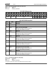
VP Memory Offset 010h
Typ e R /W
Reset Value 00000000_00000000h
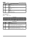
DCFG Bit Descriptions (Continued)
Bit Name Description
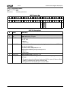
VX Register Map
63 62 61 60 59 58 57 56 55 54 53 52 51 50 49 48 47 46 45 44 43 42 41 40 39 38 37 36 35 34 33 32
RSVD
313029282726252423222120191817161514131211109876543210
RSVD VID_X_END RSVD VID_X_START
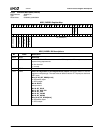
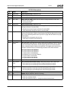
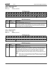
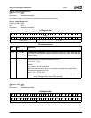
VX Bit Descriptions
Bit Name Description
63:28 RSVD (RO) Reserved (Read Only). Reads back as 0.
27:16 VID_X_END Video X End Position. Represents the horizontal end position of the video window. This
register is programmed relative to CRT horizontal sync input (not the physical screen
position). This value is calculated according to the following formula:
Value = Desired screen position + (H_TOTAL – H_SYNC_END) – 13. (Note 1)
15:12 RSVD (RO) Reserved (Read Only). Reads back as 0.
11:0 VID_X_START Video X Start Position. Represents the horizontal start position of the video window.
This value is calculated according to the following formula:
Value = Desired screen position + (H_TOTAL – H_SYNC_END) – 14. (Note 1)
Note 1. H_TOTAL and H_SYNC_END are the values written in the Display Controller module registers.


