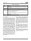
244 AMD Geode™ LX Processors Data Book
Graphics Processor
33234H
6.3.2.5 Anti-Aliased Text Support
Channel 3 can be setup to fetch 4-bpp alpha channel data
that can be combined with either 16 or 32-bpp color or
monochrome source data using the alpha unit in the GP.
The depth and type in the GP_CH3_MODE_STR register
should be setup to indicate 4-bpp alpha and the AS bits in
the GP_RASTER_MODE register (GP Memory Offset
38h[19:17]) should be set to 110 to select the alpha from
channel 3.
6.3.2.6 8x8 Color Pattern
Channel 3 can also be configured to source full color pat-
terns into the GP. The pattern data is stored in the 2K
buffer using writes to the GP_LUT_INDEX and
GP_LUT_DATA registers (GP Memory Offset 70h and
74h, respectively) as done for loading the LUT. Addresses
100h-10Fh are used for 8-bpp patterns, 100h-11Fh are
used for 16-bpp patterns and 100h-13Fh are used for 32-
bpp patterns. Note that this data will not be persistent in the
buffer. If channel 3 is later used in non-pattern mode, then
the pattern data will no longer be present in the buffer.
Therefore it is usually necessary to reload the pattern data
before any BLT requiring 8x8 color pattern support. The
depth of the pattern is determined by the BPP/FMT bits
(GP Memory Offset 64h[27:24]) of the
GP_CH3_MODE_STR register (4-bpp is not allowed in
pattern mode). The output of the pattern hardware is con-
verted to the depth specified in the BPP/FMT GP bits
(Memory Offset 38h[31:28]) of the GP_RASTER_MODE
register if the two depths do not match.
6.3.2.7 Patterned Vectors
When pattern mode is enabled during a vector operation,
channel 3 generates a patterned (stippled) vector. This is a
linear monochrome pattern that is stored in the LUT at
locations 100h and 101h. The first DWORD (100h) con-
tains the pattern, which is a string of four to 32 bits starting
at bit 0. The second DWORD is used to indicate the length
of the pattern and is a string of four to 32 ones starting at
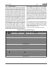
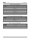
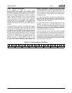
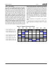
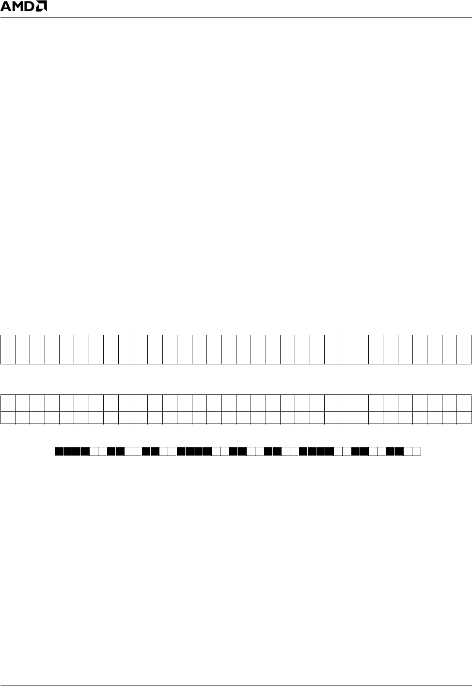
bit 0. Tables 6-14 and 6-15 show an example vector pattern
and length. The result of this vector pattern/length would be
a 14-bit long pattern that, when repeated, looks Figure 6-
11.
The dark pixels are rendered using the selected ROP,
while the light pixels are transparent. The ROP may con-
tain any combination of source, destination and pattern. If
pattern is enabled in the ROP, it comes from the old (non-
channel 3) pattern hardware. Note that a vector pattern
must be at least four pixels long. For shorter patterns (i.e.,
two on, one off), repeat the pattern in the pattern registers
until it is at least four pixels long.
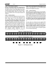
Figure 6-11. 14-Bit Repeated Pattern
Table 6-14. Example Vector Pattern
313029282726252423222120191817161514131211109876543210
00000000000000000000110011001111
Table 6-15. Example Vector Length
313029282726252423222120191817161514131211109876543210
00000000000000000011111111111111


