


402 AMD Geode™ LX Processors Data Book
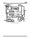
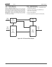
Video Processor
33234H
6.7.6.5 Operating Modes
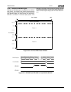
BT.656 Mode
BT.656 is the basic standard that specifies the encoding of
the control lines into the data bus. In this mode the sepa-
rate control lines are encoded into the data bus as speci-
fied by Recommendation ITU-R BT.656.
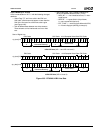
Each line begins with a Start of Active Video (SAV) header,
and ends with an End of Active Video (EAV) header. Each
of these are four-byte sequences beginning with FF, 00,
00. The fourth byte of the header provides important infor-
mation about this line. The bit format of the SAV and EAV
headers is shown in Table 6-62.
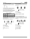
The T bit is specified in BT.656 as a constant logic 1. The F
bit indicates Field - 1 for even (also called Field 2), 0 for
odd (Field 1). The V bit indicates Vertical Blanking. The H
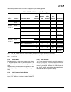
bit indicates Horizontal Blanking. Bits P3 through P0 are
protection bits used to detect and correct single-bit errors.
The bits are defined as follows:
P3 = (V + H) + ~T
P2 = (F + H) + ~T
P1 = (F + V) + ~T
P0 = (F + V) + H
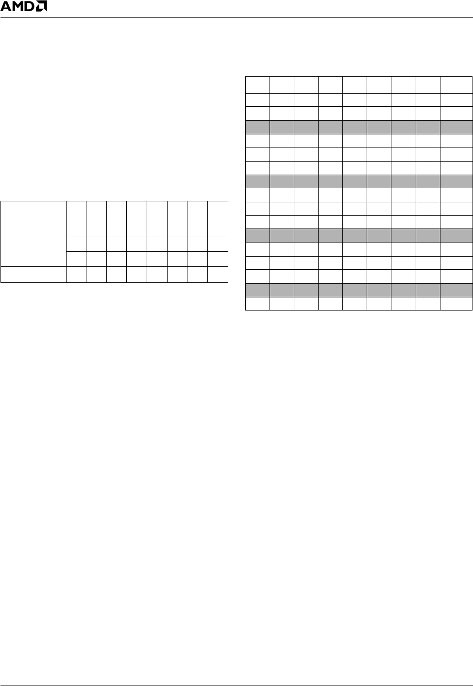
Using the above formulas, the bit values are listed in Table
6-63.
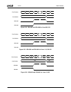
VIP 1.1 Compatible Mode
VIP 1.1 compatible mode builds on CBT.656 mode with the
following changes/additions:
— Video Flags T, F, and V can only be changed in the
EAV code. During vertical blanking there must be a
minimum of one SAV/EAV scan line in order to
convey the updated T, F, and V bits.
— Task bit is used to indicate VBI data within the video
stream (T = 0 for VBI Data, T = 1 for active video).
— P3-P0 are ignored.
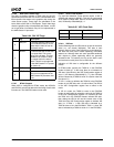
Table 6-62. SAV/EAV Sequence
Parameter D7D6D5D4D3D2D1D0
Preamble 11111111
00000000
00000000
Status Word T F V H P3 P2 P1 P0
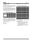
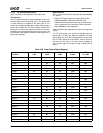
Table 6-63. Protection Bit Values
T F V H P3 P2 P1 P0 Hex
000
011
100E
000
100
11 13
0 0 1
0 0 1
0 1 25
001
110
00 38
010
010
01 49
010
101
00 54
0 1 1
0 0 0
1 0 62
011
111
11 7F
100
000
00 80
100
111
019D
1 0 1
0 1 0
1 1 AB
101
101
10B6
110
001
11C7
110
110
10DA
1 1 1
0 1 1
0 0 EC
111
100
01 F1