AMD Geode™ LX Processors Data Book 295
Display Controller
33234H
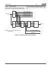
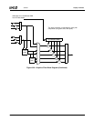
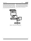
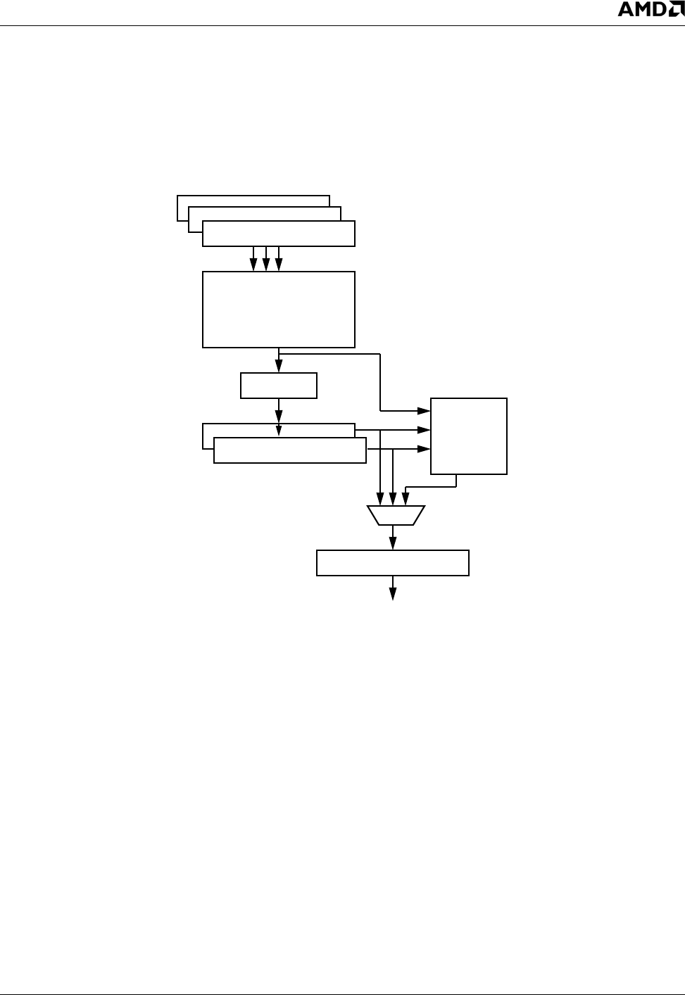
To support the flicker filter, the scaling filter then feeds two
additional line buffers. These buffers are 1024 pixels wide.
The scaling filter directly feeds a tap of the 3x1-tap flicker
filter. (The other two taps are fed by the two line buffers.) All
filtering is performed in the GeodeLink I/F clock domain.
The result from the flicker filter feeds a final line buffer,
which is used to synchronize the data stream to the Dot
clock domain. When the flicker filter is enabled, the final
image width is dictated by this final line buffer, which is
1024 pixels wide. When the flicker filter is disabled, the two
line buffers normally used to feed the flicker filter are used
as one line buffer, that feeds the final synchronizing line
buffer. This enables scaling to image sizes up to 2048 pix-
els wide, provided that interlacing is not required. Figure 6-
21 illustrates the flicker filter and line buffer path.
Figure 6-21. Flicker Filter and Line Buffer Path
1024-Pixel Line Buffers
Graphics Scaler Filter
Delay
1024-Pixel Line Buffers
3-Tap
Vertical
Flicker
Filter
1024-Pixel Line Buffers


