


Brocade Network Advisor IP User Manual 311
53-1003056-01
VLAN Topology view
8
• The snIfStpTable MIB table (OID.1.3.6.1.4.1.1991.1.1.3.5.2) is enabled on the device and has
either STP or RSTP configured. This MIB is not supported on third-party products.
Viewing STP/RSTP topology
To view this topology map, complete the following steps.
1. Select VLAN Topology from the view list on the Product List toolbar.
Pause on the STP button. A tool tip appears, indicating whether STP is on or off.
2. If STP is off, click STP to turn it on.
3. Select a VLAN or PVLAN from the VLAN Product List.
All devices with STP mode on the selected VLAN display on the map, regardless of their
connectivity. STP-enabled devices display with a Bridge ID.
The STP Topology view supports both STP and RSTP; however, the map does not differentiate
between the two protocols. You can use the STP/RSTP report to determine which protocol is
enabled on a device. MSTP protocol is not supported.
When STP mode is active, dynamic updates is not active. Instead, a Refresh button displays on
the Topology Map toolbar, next to the STP button, to enable you to manually trigger an update.
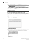
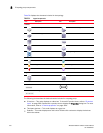
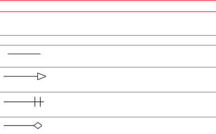
Table 33 displays the elements of the STP Topology map.
TABLE 33 STP/RSTP Topology map elements
Element Description
Device name
IP address
Bridge ID
Each device on the map displays its device name, IP address and bridge ID.
[Root] The root bridge.
solid line
The bridges on the topology in normal operating state.
link with arrow head
The port is in a forwarding state and has the root port role.
link with block
The port is in a blocking state or discarding.
link with diamond
The port is in a disabled state.