12-4
Cisco ASR 1000 Series Aggregation Services Routers Software Configuration Guide
OL-16506-17
Chapter 12 IEEE 1588v2 PTP Support
Information About IEEE 1588v2 PTP
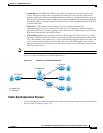
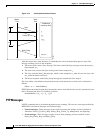
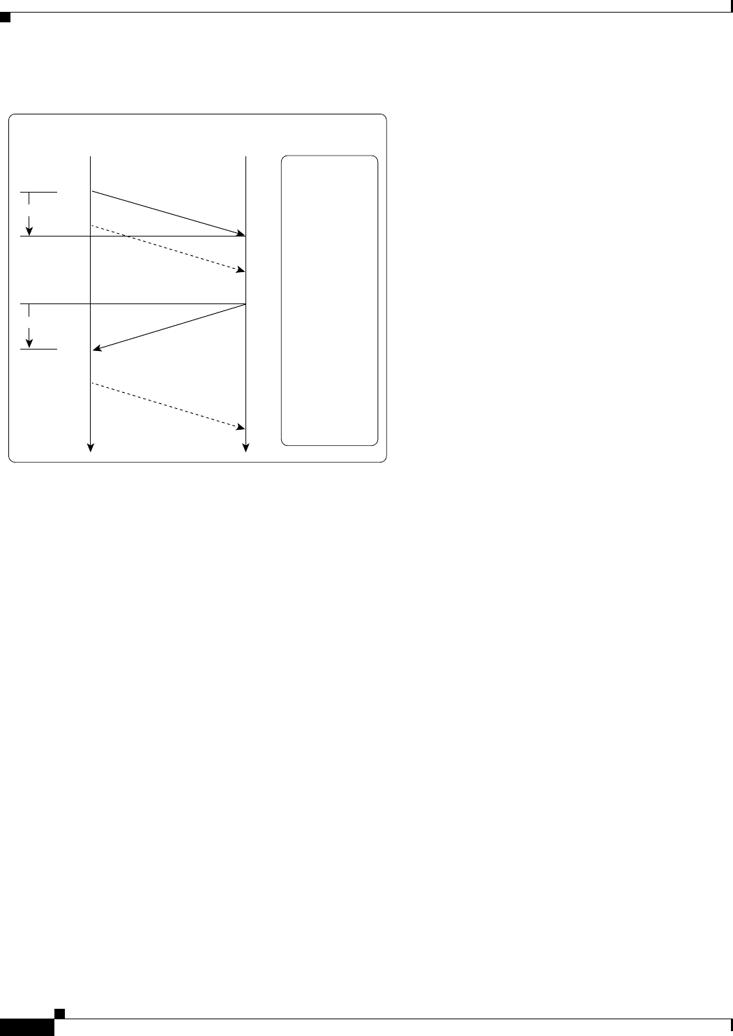
Figure 12-2 Clock-Synchronization Process
After the master-slave clock hierarchy is established, the clock synchronization process starts. The
message exchange occurs in this sequence:
1. The master clock sends a Sync message. The time at which the Sync message leaves the master is
time-stamped as t
1
.
2. The slave clock receives the Sync message and is time-stamped as t
2.
.
3. The slave sends the Delay_Req message, which is time-stamped as t
3
when it leaves the slave, and
as t
4
when the master receives it.
4. The master responds with a Delay_Resp message that contains the time stamp t
4
.
The clock offset is the difference between the master clock and the slave clock, and is calculated as
follows:
Offset = t
2
- t
1
- meanPathDelay
IEEE1588 assumes that the path delay between the master clock and the slave clock is symmetrical, and
hence, the mean path delay is calculated as follows:
meanPathDelay = ((t
2
- t
1
) + (t
4
- t
3
))/2
PTP Messages
All PTP communication is performed through message exchange. The two sets of messages defined by
IEEE1588v2 are General messages and Event messages.
• General messages--These messages do not require accurate time stamps, and are classified as
Announce, Follow_Up, Delay_Resp, Pdelay_Resp_Follow_Up, Management, and Signaling.
• Event messages--These messages require accurate time stamping, and are classified as Sync,
Delay_Req, Pdelay_Req, and Pdelay_Resp.
Timestamps
known by slave
Slave
Time
Master
Time
t
1
t
1
t
2
t
2
t
1
,t
2
,t
3
t
1
,t
2
,t
3
,t
4
t
1
,t
2
t
2
Sync
Follow_Up
Delay_Resp
Delay_Req
t-ms
t-ms
372867


