


16-7
Cisco ASR 1000 Series Aggregation Services Routers Software Configuration Guide
OL-16506-17
Chapter 16 Configuring MPLS Layer 2 VPNs
Virtual Private LAN Services
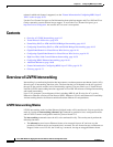
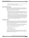
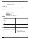
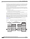
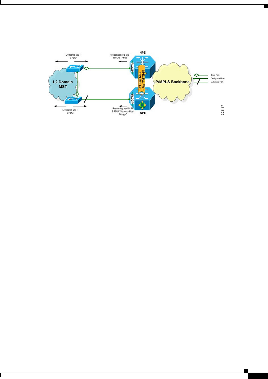
Figure 16-2 shows how a BPDU is forwarded to an R-L2GP port.
Figure 16-2 BPDU on an R-L2GP Port
BPDUs Received on R-L2GP Ports
On PE, only BPDUs with Topology Change Notification (TCN) bits on are punted to the R-L2GP and
the STP module. If the PE is in a redundant setting, the corresponding BPDUs are is propagated to
peer-redundant PE via the L2 protocol forwarding pseudowire (PW).
BPDUs Received on L2 Protocol Forwarding PW
The TCN BPDUs received from L2 protocol forwarding PW are punted to RP, and STP/R-L2GP process
it and generate MAC flush.
Restrictions for R-L2GP
The restrictions for the R-L2GP feature are:
• R-L2GP is supported only on L2 bridge ports, and is not compatible with prestandard MST.
• All the access-side shall have the same MST instance, the same name and the same revision number
configuration as nPEs.
• There is no configure error detection and recover mechanism for R-L2GP. Users are expected to
configure R-L2GP and MSTP instance on CEs and nPEs correctly.
Configuring the R-L2GP
Since the R-L2GP configuration is bundled with the MST configuration, the above parameters can be
recycled from the MSTI and MST region (currently only one MST region is supported on IOS)
configurations. This section describes how to configure Reverse L2GP. It consists of the following
sections:
• Configuring the MST, page 16-8
• Configuring an R-L2GP Instance, page 16-9
• Attaching an R-L2GP Instance to a Port, page 16-10
• Example: Configuring an R-L2GP, page 16-11