


16-14
Cisco ASR 1000 Series Aggregation Services Routers Software Configuration Guide
OL-16506-17
Chapter 16 Configuring MPLS Layer 2 VPNs
Frame Relay DLCI-to-ATM AAL5SNAP Bridged Interworking
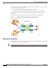
On the FR PE router with interworking function, when traffic flows from the FR segment to the MPLS
cloud, the bridged encapsulation (Frame Relay and SNAP header) is discarded and the Ethernet frame
is encapsulated with the labels required to go through the pseudowire, using the VC type 5 (Ethernet).
In the opposite direction, after the label disposition from the MPLS cloud, the Ethernet frames are
encapsulated over FR using bridged encapsulation.
The PE router automatically supports translation of both Cisco and IETF Frame Relay encapsulation
types coming from the Customer edge (CE) router, but translates only to IETF when sending to the CE
router. The Cisco CE router can handle the IETF encapsulation on receipt, even if it is configured to send
Cisco encapsulation.
The following modes are supported:
• The ATM permanent virtual circuit (PVC) mode with the AAL5SNAP encapsulation type, and the
existing Quality of Service (QoS) functionality for ATM PVCs.
• The Frame Relay DLCI mode, and the existing QoS functionality for Frame Relay.
PVC status signaling works the same way it does in the like-to-like case. The PE router reports the PVC
status to the CE router, based on the availability of the pseudowire.
The attachment circuit maximum transmission unit (MTU) on both sides of the pseudowire must match
when connected over MPLS. The non-AAL5 traffic (such as OAM cells) is punted to be processed at the
RP level. A VC that is configured with OAM cell emulation on the ATM PE router (using the oam-ac
emulation-enable command) can send end-to-end F5 loopback cells at configured intervals toward the
CE router. When the pseudowire is down, an end-to-end F5 segment alarm indication signal (AIS) and
remote defect indication (RDI) is sent from the PE router to the CE router.
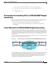
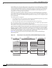
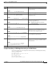
Figure 16-4 shows the protocol stack for the Frame Relay DLCI-to-ATM AAL5SNAP Bridged
Interworking feature.
Figure 16-4 Protocol Stack for Frame Relay DLCI-to-ATM AAL5SNAP Bridged Interworking
331936
ATM
CE
ATM
ATM
PE
FR
PE
FR
CE
Frame Relay
MPLS
Emulated VC of type 5
ATM Header
MAC Header
DA
SA
Ethertype 81-00
VLAN Tag
CPCS-UU CPI
Length
CRC
Ethertype 81-00
VLAN Tag
MAC Header
DA
SA
Type/Length Type/Length
Ethertype 81-00
VLAN Tag
Type/Length
Ethertype 81-00
VLAN Tag
Type/Length
Remainder of
MAC Frame
Remainder of
MAC Frame
Remainder of
MAC Frame
Remainder of
MAC Frame
LLC (AA-AA)
LLC (03) OU I (00)
CUI (80-C2)
PID (00-007)
PAD (00-00)
Control Word
Tunnel Label
VC Label
MAC Header
DA
SA
Control Word
Tunnel Label
VC Label
MAC Header
Frame Relay Header
Q.922 Address
DA
SA
Ctrl (03 | Pad(03)
NL PD (80) | OUT (00)
OUT (80-C2)
PID (00-007)
FCS