


12-11
Cisco ASR 1000 Series Aggregation Services Routers Software Configuration Guide
OL-16506-17
Chapter 12 IEEE 1588v2 PTP Support
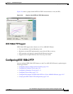
Configuring IEEE 1588v2 PTP
Examples
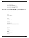
The following example shows how to configure an ordinary clock as PTP slave:
Router# configure terminal
Router(config)# ptp clock ordinary domain 0
Router(config-ptp-clk)# clock-port SLAVE master
Router(config-ptp-port)# transport ipv4 unicast interface Loopback22 negotiation
Router(config-ptp-port)# clock source 10.10.10.10
Router(config-ptp-port)# end
Configuring a Boundary Clock
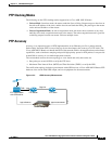
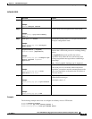
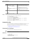
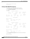
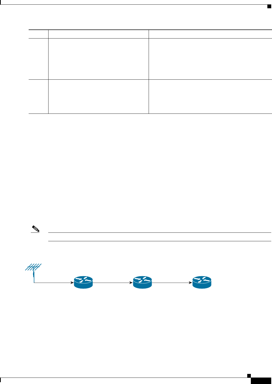
You can configure the PTP master and PTP slave in a boundary clock topology as shown in Figure 12-8
in the same way that you configure a master and slave in ordinary clock mode. This section describes
how to configure a Cisco ASR 1002-X Router in boundary clock mode.
Note Currently, boundary clock supports only unicast negotiation mode.
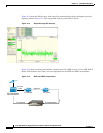
Figure 12-8 PTP Boundary Clock Scenario
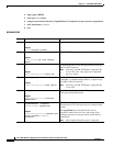
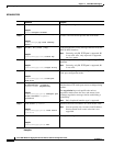
SUMMARY STEPS
1. configure terminal
2. ptp clock boundary domain domain_number
3. clock-port name slave
4. transport ipv4 unicast interface {GigabitEthernet | Loopback} interface-number {negotiation}
5. clock source ip-address
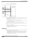
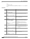
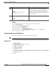
Step 5
clock source ip-address
Example:
Router(config-ptp-port)# clock source
10.10.10.10
Specifies the source IP address of a PTP master clock.
Note You can specify only 1 master clock IP address.
Priority-based clock source selection is not
supported.
Step 6
end
Example:
Router(config-ptp-port)# end
Exits global configuration mode.
Command Purpose
PTP Boundary NodePTP Master
Gige linkClock E1/10MHz
GPS antenna
PTP Slave
Gige link
372866