


1-48
Cisco MGX 8800/8900 Series Hardware Installation Guide
Releases 2 - 5.2, Part Number OL-4545-01, Rev. H0, May 2006
Chapter 1 Product Overviews
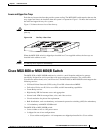
Cisco MGX 8830 or MGX 8830/B Switch
Standards-Based Conversion to ATM
The MGX 8830 or MGX 8830/B switch converts all user information into 53-byte ATM cells by using
the appropriate ATM adaptation layer (AAL) for transport over the ATM backbone network. The
individual service modules segmentation and reassembly (SAR) cells to eliminate system bottlenecks.
The following list shows the applicable AAL for each service:
• Circuit emulation services uses AAL1.
• Frame Relay-to-ATM network interworking uses AAL5 and Frame Relay Service Specific
Convergence Sublayer (FR-SSCS).
• Frame Relay-to-ATM service interworking uses both transparent and translation modes to map
Frame Relay to native ATM AAL5.
• Frame Forwarding uses AAL5.
• VISM voice applications can use AAL or AAL2 for VoATM, or AAL5 for VoIP.
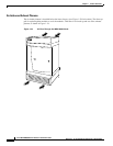
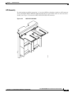
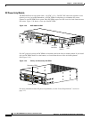
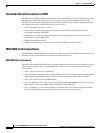
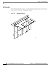
MGX 8830 Card Compartment
The MGX 8830 or MGX 8830/B card compartment with cards installed in both the front and back. The
mechanical design accommodates both single and double-height cards.
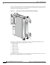
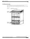
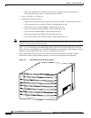
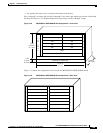
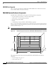
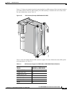
MGX 8830 Slot Assignments
The MGX 8830 and MGX 8830/B have seven double-height front card slots, most of which also support
single-height cards, and fourteen single-height back card slots. Front card slots have the following
characteristics:
• Slots 1 and 2 are reserved for PXM cards
• Slots 3 through 6 (and 10 through 13) support RPM cards or service modules, and can accommodate
either single or double-height cards. To install a double-height card, remove the slot divider.
• Slots 7 and 14 are reserved for SRM modules.
• For 1:N redundancy, Slots 5 and 12 are reserved for the redundant MPSM-16-T1E1 front card, and
the redundancy back card. (MGX 8830/B with RCON-1TO3-8830 only)
• For 1:1 redundancy, service modules must be in adjacent slots. You can best utilize the available
slots by installing redundant pairs in the bottom or top two service module slots.