


6-22
Cisco MGX 8800/8900 Series Hardware Installation Guide
Releases 2 - 5.2, Part Number OL-4545-01, Rev. H0, May 2006
Chapter 6 Maintaining the Cisco MGX Switch or Gateway
Installing or Removing Redundancy Connectors
Installing or Removing Redundancy Connectors
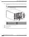
Redundancy connectors (RCON) provide 1:N redundancy for MPSM-16-T1E1 cards in MGX 8850/B
and MGX 8830/B switches.
The following types of RCONs are available:
• RCON-1TO5-8850—1:5 redundancy for the MGX 8850/B
• RCON-1TO3-8850—1:3 redundancy for the MGX 8850/B
• RCON-1TO3-8830—1:3 redundancy for the MGX 8830/B
Note The MGX 8850 and MGX 8830 do not support RCONs.
When to Install or Remove RCONs
Normally, you don’t need to install or remove RCONs. If you ordered MGX 8850/B or MGX 8830/B
switch with RCONs, they are preinstalled before delivery. However, you might change RCONs under the
following circumstances:
• Install RCONs to create another 1:N redundancy group of MPSM-16-T1E1 cards.
• Remove RCONs to make room for an APS redundancy connector.
• Move RCONs to a different location than the factory-installed default.
• Restore RCONs after backplane replacement.
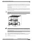
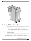
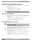
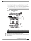
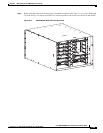
Installing MGX 8850/B Redundancy Connectors
Warning
You must remove power from the MGX 8850/B switch before installing RCONs. Exposed connector pins
near the RCON have hazardous voltages.
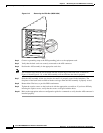
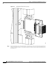
To install RCONs in the MGX 8850/B chassis, perform the following steps:
Step 1 Verify that you have an MGX 8850/B chassis. A simple check is to open a configuration session and
enter the dspcd command. The second line displays the chassis type.
Step 2 Power down the MGX 8850/B switch, either at the AC power supply or DC power source.
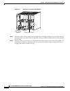
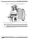
Step 3 If the MGX 8850/B has back cards installed where you want to install RCONs, remove them. For each
card, perform the following steps:
a. Use the flat-head or Phillips tip of the 3-in-1 tool to loosen the two captive screws located on the top
and bottom of the back card faceplate.
b. Pull each of the two extractor levers, located at the top and bottom of the faceplate, out to the
horizontal position.
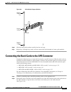
c. Pull evenly on the two extractor levers to remove the back card from the APS connector.