


4-4
Cisco MGX 8800/8900 Series Hardware Installation Guide
Releases 2 - 5.2, Part Number OL-4545-01, Rev. H0, May 2006
Chapter 4 Planning for Card Redundancy, Line Redundancy, and Bulk Distribution
Planning Standalone and Redundant Card Configurations
Standalone Card Configuration Guidelines
When a card is inserted in a switch without a standby or redundant card, it operates in standalone mode.
If a standalone card goes down, all the connections on that card will fail and traffic will be lost. All cards
that can be installed in an MGX switch can operate in standalone mode. However, Cisco recommends
configuring redundancy to ensure that you will not lose traffic and connectivity in the event of a card or
line failure.
All Cisco MGX 8850switch cards operate in the standalone configuration without additional
configuration. Standalone configurations are often used in lab environments or other non-critical
applications.
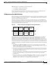
In the standalone configuration, the appropriate back cards must be installed according to the following
guidelines:
• For all PXM cards, both back cards must be installed.
• For AXSM, FRSM12, and VXSM cards that support two back cards, at least one back card must be
installed.
• For RPM cards, install back cards according to the requirements for your installation.
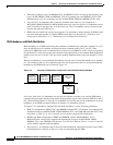
• For MGX 8880 installations, redundancy back cards must be installed in slots 4 an 20, and this
makes front card slot 4 impractical for standalone use. (Technically, a standalone card in slot 4 can
connect to back cards in slot 3, but it is more practical and intuitive to have all standalone front and
back cards in slot 3.)
• For all other service modules, one back card must be installed or bulk distribution must be
configured.
SRM cards are optional and add 1:N card redundancy, bulk distribution, and bit error rate testing (BERT)
services to a Cisco MGX 8850switch. These services apply to select service modules, so in a MGX 8850
(PXM45) switch, for example, you can install a standalone PXM and still support 1:N card redundancy
for select service modules.
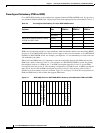
When you install SRM cards, it is important to note the relationship between the SRM cards and the
PXM cards, which is shown in Table 4-2. For example, in a MGX 8850 (PXM1E) switch, the PXM in
slot 7 is preconfigured to work with SRMs in slots 15 and 31. The SRM in slot 15 provides SRM services
to the upper bay, and the SRM in slot 31 provides SRM services in the lower bay.
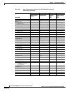
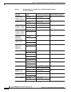
Table 4-2 Preconfigured Relationship Between PXM and SRM Cards
Switch PXM Slot
Upper Bay
SRM Slot
Lower Bay
SRM Slot
MGX 8830 and MGX8830/B 1 7 —
214—
MGX 8850 (PXM1E/PXM45), MGX 8850/B, and MGX 8880 7 15 31
81632