


1-66
Cisco MGX 8800/8900 Series Hardware Installation Guide
Releases 2 - 5.2, Part Number OL-4545-01, Rev. H0, May 2006
Chapter 1 Product Overviews
Cisco MGX 8880 Media Gateway
MGX 8880 Hardware Components
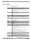
The MGX 8880 Media Gateway supports the following hardware components:
• AC power supply tray (optional)—With power supply modules
• Air intake plenum (3.5 inches, 2RU)
• APS connector—For line redundancy (optional)
• DC power entry module (PEM)
• Exhaust plenum (a combined exhaust plenum and fan tray, 3.5 inches, 2 RU)
• Redundancy connector (RCON-1TO5-8850), a keyed, built-in RCON that enables redundancy for
the cards in slots 1–6 and 17–22. See “How the Built-in MGX 8880 Redundancy Connector Affects
Module Configurations” section on page 1-73 for more information.
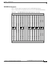
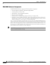
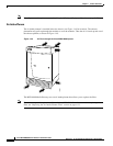
Figure 1-46 shows the hardware components that can be used with a Cisco MGX 8880 Media Gateway
(viewed from the front). This illustration also shows the optional AC power supply tray installed at the
bottom of the system. The gateway can have an optional front door installed (as shown in Figure 1-46).
For the gateway to be EMI compliant, either the optional front door must be installed on the gateway or
blank faceplates must be installed to cover any empty slots.
Note The DC PEM is installed at the rear of the chassis. The APS assembly is not visible in the illustration
because it is installed inside the card cage.