


B-5
Cisco MGX 8800/8900 Series Hardware Installation Guide
Releases 2 - 5.2, Part Number OL-4545-01, Rev. H0, May 2006
Appendix
Control and Clock Cabling
Null Modem Cable
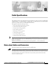
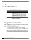
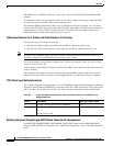
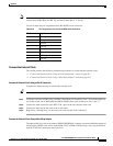
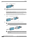
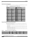
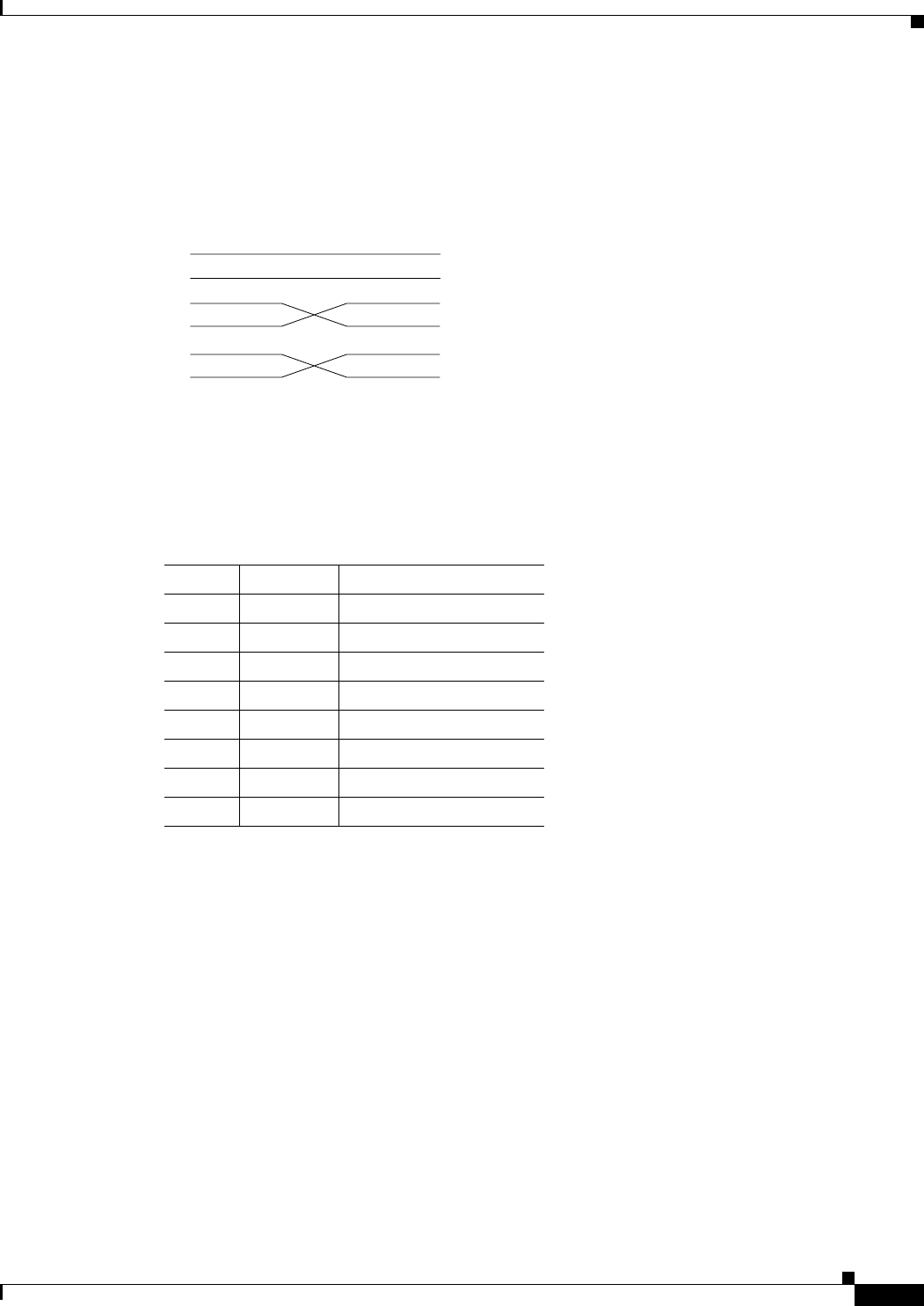
Figure B-1 shows a null modem cable that is used for connecting modems to the control or maintenance
ports on the PXM-UI-S3 and PXM-UI-S3/B User Interface Cards.
Figure B-1 Null Modem Cable
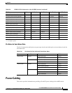
Pin Assignments for RJ-48 Maintenance and Control Ports
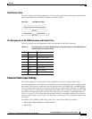
Table B-4 provides the pin assignments for the associated RJ-48 and RJ-45 connectors.
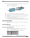
External Clock Input Cabling
This section explains the cabling that provides the MGX switch with an external clock source.
If external equipment or a local digital central office provides synchronization to the Cisco MGX switch,
the external clock source is connected to the user interface back card (PXM-UI-S3 or PXM-UI-S3/B).
The user interface back card has two external clock input ports labeled EXT CLK1 and EXT CLK2 that
can support either T1 or E1 external clock input, but not both. That is, both EXT CLK1 and EXT CLK2
clocks must be set the same, either T1 or E1. The clock may be 1.544 Mbps or 2.048 Mbps. Refer to
Table 2-44 on page 2-120 for information about which switch is compatible with which user interface
back card, and see Figure 2-63 on page 2-121 and Figure 2-64 on page 2-122 for locations of the external
clock ports.
The PXM-UI-S3 or PXM-UI-S3/B cards go into slots 7 and 8 for the following switches:
• MGX 8850 (PXM1E/PXM45) and MGX 8850/B
• MGX 8950
1
7
2
3
6
20
1
7
2
3
6
20
S6189
Table B-4 Pin Assignments for the RJ-48 Maintenance and Control Ports on the PXM-UI-S3 and
PXM-UI-S3/B User Interface Cards
Pin No. Name Description
1 RTS out Request to send
2 DTR out Data terminal ready
3 TxD Transmit data
4 GND Chassis ground
5 GND Chassis ground
6 RxD Receive data
7 DSR Data set ready
8CTSClear to send