


5-61
Cisco MGX 8800/8900 Series Hardware Installation Guide
Releases 2 - 5.2, Part Number OL-4545-01, Rev. H0, May 2006
Chapter 5 Installing the Cisco MGX Switch or Gateway
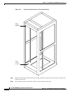
Installing the MGX 8950 Switch
—If the rack is provided with stabilizing devices, install the stabilizers before mounting or servicing
the unit in the rack.
Statement 1006
Install the AC Power Supply Tray
Note AC power supply trays are optional for the MGX 8950 switch. If your system uses only DC power,
proceed to the “Install the Air Intake Plenum” section on page 5-64.
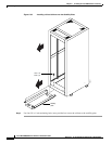
Before installing the AC power supply tray, you should remove the power supplies from the tray.
Removing the AC power supplies makes the AC power tray easier to install. For a mid-mount
installation, you must remove the power supplies from the power supply tray before installing the tray.
This section contains the following procedures:
• Remove the AC Power Supplies from the AC Power Supply Tray, page 5-61
• Install the AC Supply Power Tray(s), page 5-62
• Reinstall the AC Power Supplies, page 5-63
Tip If a component requires more than two screws for installation in the rack or cabinet, install the two
bottom screws first.
Warning
Before working on a system that has an On/Off switch, turn OFF the power and unplug the power cord.
Statement 1
Warning
Never install an AC power module and a DC power module in the same chassis.
Statement 264
Warning
Before working on a chassis or working near power supplies, unplug the power cord on AC units;
disconnect the power at the circuit breaker on DC units.
Statement 12
Remove the AC Power Supplies from the AC Power Supply Tray
Tip Before removing the AC power supplies from the tray, record the location of each power supply.
Complete the following steps to remove an AC power supply from the AC power supply tray:
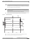
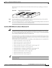
Step 1 Place the AC power supply tray on a flat and stable surface (for example, a table top).
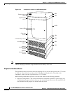
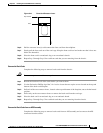
Step 2 Insert a small flat-blade (0.20 inch wide maximum) screwdriver in the access hole at the top of the air
intake grille, as shown in Figure 5-38. Rotate the screwdriver in either direction until the latch opens.