


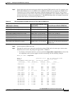

6-7
Cisco MGX 8800/8900 Series Hardware Installation Guide
Releases 2 - 5.2, Part Number OL-4545-01, Rev. H0, May 2006
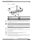
Chapter 6 Maintaining the Cisco MGX Switch or Gateway
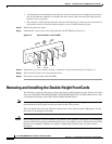
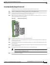
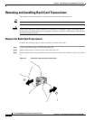
Removing and Installing the Double-Height Front Cards
Install the Double-Height Front Cards
Complete the following steps to install double-height front cards in the chassis:
Step 1 Connect a grounding strap to the ESD grounding jack or to the equipment rack.
Step 2 Verify that there are no bent pins, bent dividers, or damaged connectors on the front cards (see the “Card
Installation and Replacement Suggestions” section on page 3-8).
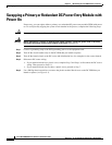
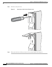
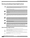
Step 3 Remove the plastic protective cover from the rear edge of the card, as shown in Figure 6-4. This cover
protects the alignment tabs during shipping.
Figure 6-4 Protective Cover Removal
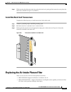
Step 4 Verify that the extractor levers are in the unlatched position.
Step 5 Position the front card over the appropriate slot and align the front card edge with the slot guides (top
and bottom) in the chassis.
Step 6 Lift up and out on the extractor levers and gently apply pressure to the faceplate while pushing the front
card into the slot.
Step 7 After the front card is installed in the chassis, apply even pressure to the top and bottom of the faceplate
to fully seat the front card.
Step 8 Press down on the extractor levers until they latch to secure the front card.
Note If you are installing the front card for the first time, refer to the configuration procedures in the
appropriate software configuration guide.
Step 9 Close the front door, if present.
84165