


5-86
Cisco MGX 8800/8900 Series Hardware Installation Guide
Releases 2 - 5.2, Part Number OL-4545-01, Rev. H0, May 2006
Chapter 5 Installing the Cisco MGX Switch or Gateway
Installing the MGX 8950 Switch
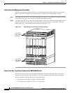
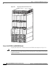
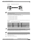
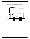
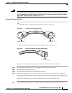
Step 3 Route the cable outside the cable management brackets, then insert the other end of the cable labeled
“PEM 1 J1” into the primary (bottom) PEM receptacle labelled “J1.”
Push the connector in to seat it
Step 4 Tighten the captive screws firmly by hand.
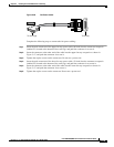
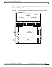
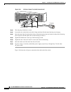
Step 5 Insert the connector labeled “Card Cage B1” into the card cage receptacle labeled “PSB 1.”
Push the connector in to seat it.
Step 6 Tighten the captive screws firmly by hand.
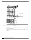
Step 7 Insert the other end of the cable labeled “PEM 2 J1” into the secondary (top) PEM receptacle labeled
“J1.”
Step 8 Tighten the captive screws firmly by hand.
Step 9 Insert the connector labeled “Card Cage B2” into the card cage receptacle labeled “PSB 2.”
Push the connector in to seat it.
Step 10 Tighten the captive screws firmly by hand.
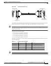
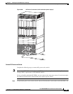
Step 11 Insert the other end of the cable labeled “PEM 2 J2” into the secondary (top) PEM receptacle labeled
“J2.”
Push the connector in to seat it.
Step 12 Tighten the captive screws firmly by hand.
Step 13 Insert the connector labeled “Card Cage A2” into the card cage receptacle labeled “PSA 2.”
Push the connector in to seat it.
Step 14 Tighten the captive screws firmly by hand.
Step 15 Route cable outside the cable management system brackets, then insert the other end of the cable labeled
“PEM 1 J2” into the primary (lower) PEM receptacle labeled “J2.”