


1-35
Cisco MGX 8800/8900 Series Hardware Installation Guide
Releases 2 - 5.2, Part Number OL-4545-01, Rev. H0, May 2006
Chapter 1 Product Overviews
Cisco MGX 8950 Switch
• Is shipped in one of two configurations:
–
Cisco cabinet configuration—All components are shipped preinstalled in a Cisco cabinet.
–
Open rack configuration—Individual components are shipped ready for installation in a
customer-supplied open rack or a third-party vendor cabinet.
• Fits in a 19-inch or a 23-inch rack
• Supports the following modules:
–
ATM switching service module (AXSM)
–
Processor switching module (PXM45/B or PXM45/C)
–
Route processor module–premium (RPM-PR)
–
Route processor module–express forwarding (RPM-XF)
–
XM60
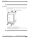
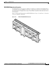
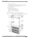
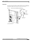
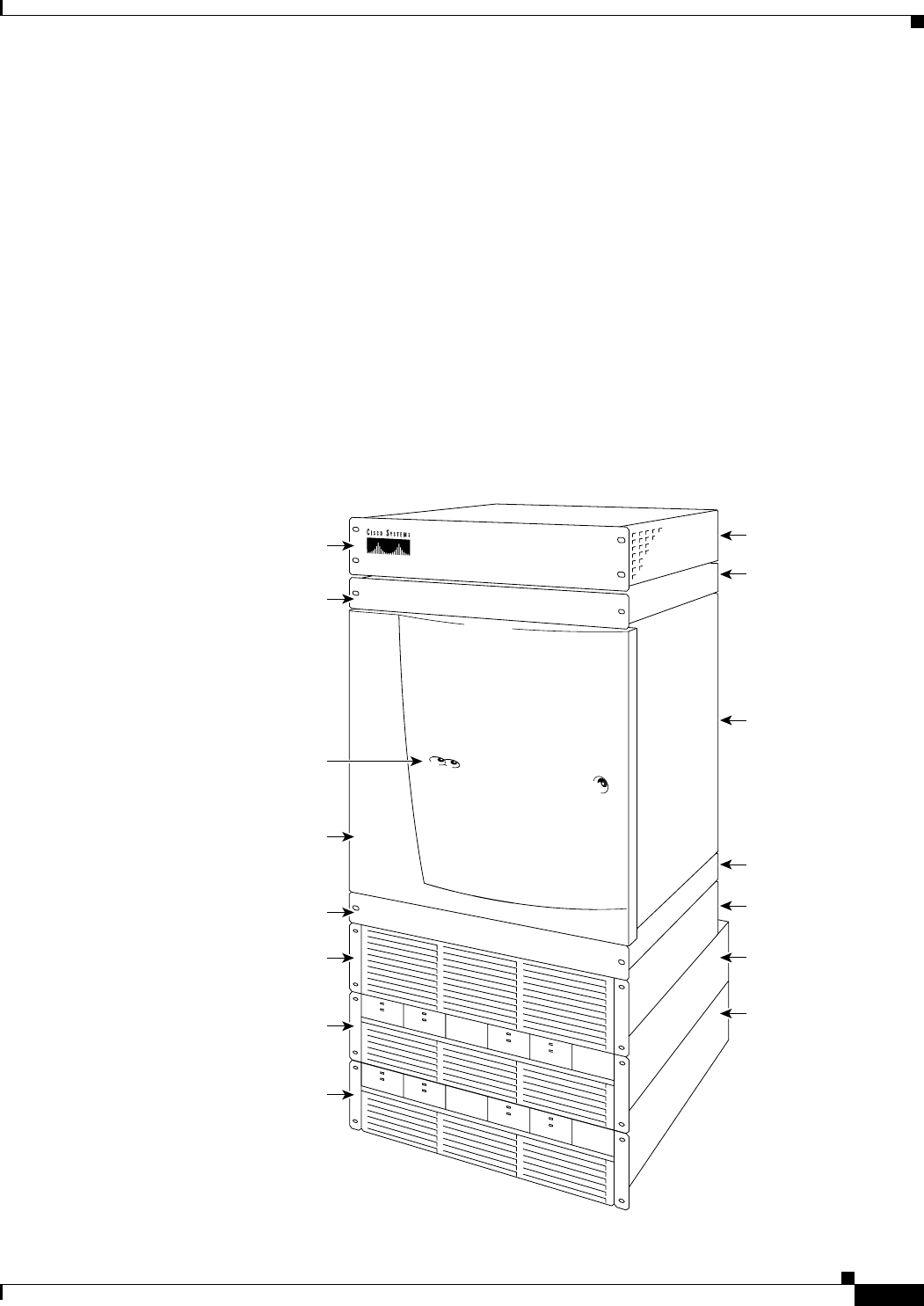
Figure 1-20 shows the MGX 8950 switch and corresponding hardware components.
Figure 1-20 Hardware Component Locations for a Cisco MGX 8950 Switch—AC-Powered Version
43977
A
C
D
C
1200W
A
C
D
C
1
2
0
0
W
A
C
D
C
1200W
A
C
D
C
1200W
A
C
D
C
1200W
A
C
DC
1200W
AC
DC
1
2
0
0
W
A
C
D
C
1
2
0
0
W
Exhaust plenum
3.5 in.
2 RU
1 RU
10 RU
1 RU
3 RU
3 RU
3 RU
Upper fan tray
1.75 in.
Lower fan tray. 1.75 in.
Card cage
17.5 in.
Air intake plenum
5.25 in.
Optional
AC power tray
5.25 in
Optional
AC power tray
5.25 in
Status LEDs