


5-123
Cisco MGX 8800/8900 Series Hardware Installation Guide
Releases 2 - 5.2, Part Number OL-4545-01, Rev. H0, May 2006
Chapter 5 Installing the Cisco MGX Switch or Gateway
Installing the MGX 8830 or MGX 8830/B Switch
If you are using AC power, complete the following steps to connect the AC power supply tray to the
MGX 8830 switch. If you are using DC power, proceed to the “Connect the Back Cards” section on
page 5-124.
Note One end of the AC power supply cable has a fixture that installs in the DC PEM slots of the switch. The
other end of the cable attaches to the AC power supply.
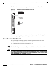
Step 1 Position the fixture, located on the end of an AC power supply cable, over a DC PEM slot guides and
align the fixture edge with the slot guides (left and right) in the chassis.
Step 2 Gently apply even pressure to the sides of the faceplate while pushing the fixture into the slot.
Step 3 Once the fixture is installed in the switch, apply even pressure to the sides of the faceplate to fully seat
the fixture.
Step 4 Use the flat-head or Phillips tip of the 3-in-1 tool to tighten the two captive screws on the
fixture faceplate. Do not overtighten the screws or use a power screwdriver.
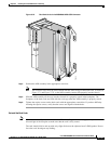
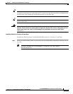
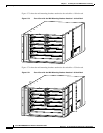
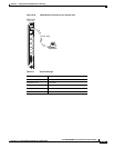
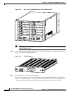
Figure 5-77 shows the fixtures installed in the rear of the switch.
Note Without the AC power supply cable connected to the MGX 8830 midplane, through use of the
fixture, the AC power supply will not power up. This is a safety feature.
Figure 5-77 Two AC Power Supplies Installed in the MGX 8830 Switch
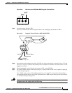
Step 5 Connect the other end of the AC power supply cable to the AC power supply.
A
C
D
C
A
C
D
C
23825