


3-27
Cisco MGX 8800/8900 Series Hardware Installation Guide
Releases 2 - 5.2, Part Number OL-4545-01, Rev. H0, May 2006
Chapter 3 Preparing for Installation
Site Requirements for the MGX 8850 or MGX 8850/B Switch
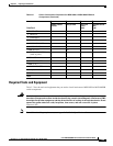
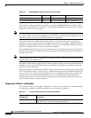
AC power cord for AC power supply tray, optional for AC power:
• Argentina: Cisco Part Number CAB-ACR
• Australia: Cisco Part Number PWRCD-ANZ
• Continental Europe: Cisco Part Number PWRCD-EU
• Great Britain: Cisco Part Number PWRCD-GBI
• Ireland: Cisco Part Number PWRCD-GBI
• Italy: Cisco Part Number PWRCD-IT
• Japan: Cisco Part Number PWRCD-NA
• New Zealand: Cisco Part Number PWRCD-ANZ
• North America: Cisco Part Number PWRCD-NA (NEMA L6-20 twistlock plug)
Wire for DC power connection—6 AWG (10 square mm) or larger three-wire solid or
stranded copper wire with insulation rating for 140°F (60°C)
Stability plate kit, optional—Cisco Part Number STRATM-STAB
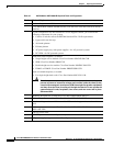
ESD protection equipment—Required whenever you handle Cisco equipment, which
includes the switch, cards, and modules
Mounting screws—To mount the Cisco MGX 8850 switch, upper fan tray, lower fan tray,
air intake plenum, exhaust plenum, and optional AC power supply tray in the rack
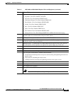
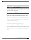
Tools
Small- and medium-sized flat-blade screwdrivers
Small- and medium-sized Phillips screwdrivers
3-in-1 tool (part 700-07569-01) with the following heads:
• A flat head for unlatching front card ejectors and loosening and tightening the back card
captive screws
• A hex head for unlatching the chassis door
• A Phillips head for loosening and tightening the back card captive screws
Power screwdriver, optional
Wire stripper
Wire-wrapping tool, optional
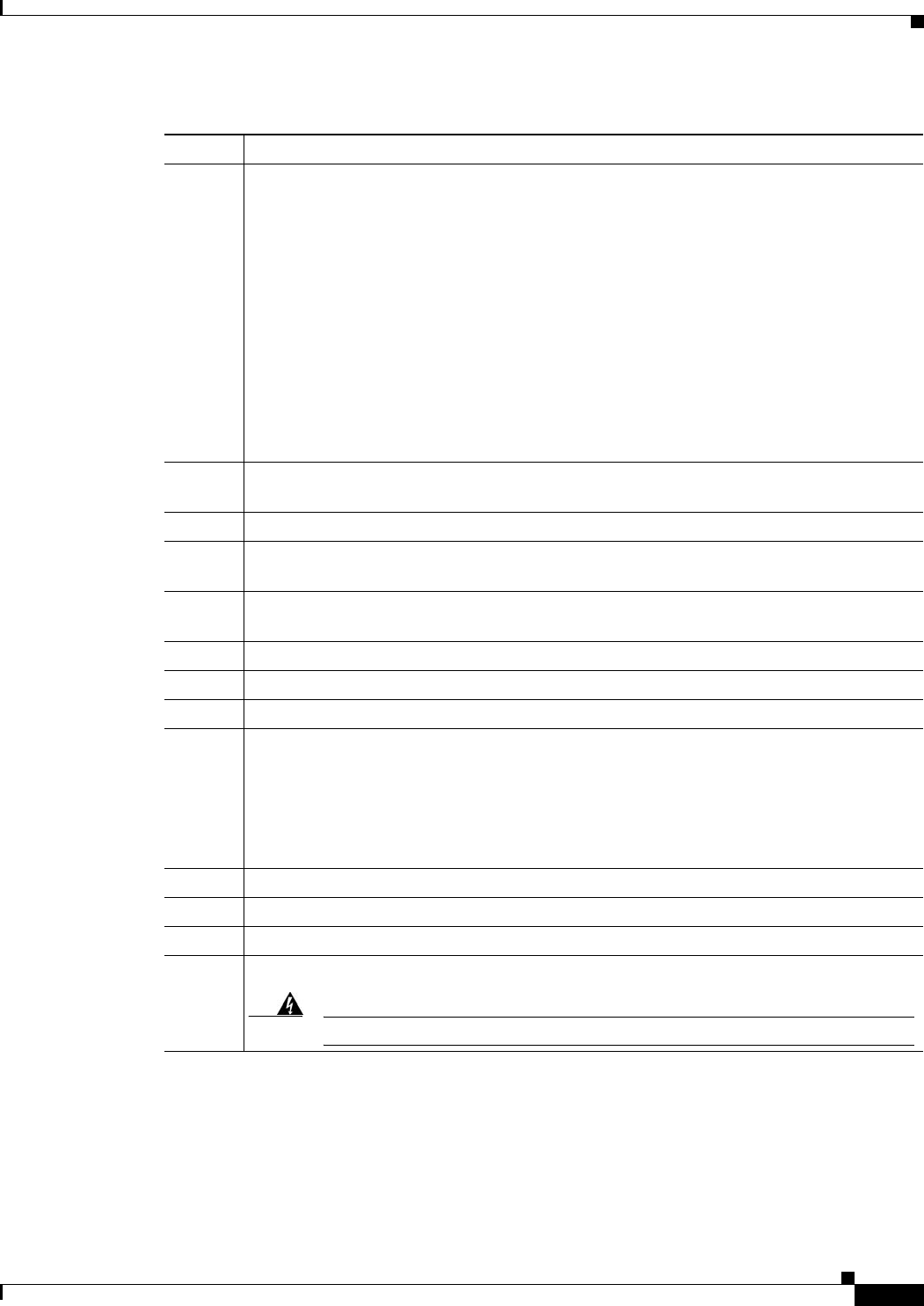
Fuse replacement tool (218090-00).
Warning
This tool should only be used by trained personnel.
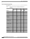
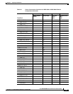
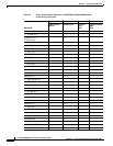
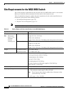
Table 3-7 MGX 8850 or MGX 8850/B Required Tools and Equipment (continued)
Check Tools and Equipment