


6-17
Cisco MGX 8800/8900 Series Hardware Installation Guide
Releases 2 - 5.2, Part Number OL-4545-01, Rev. H0, May 2006
Chapter 6 Maintaining the Cisco MGX Switch or Gateway
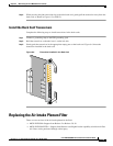
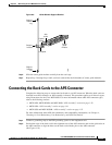
Connecting the Back Cards to the APS Connector
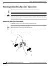
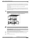
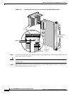
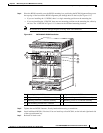
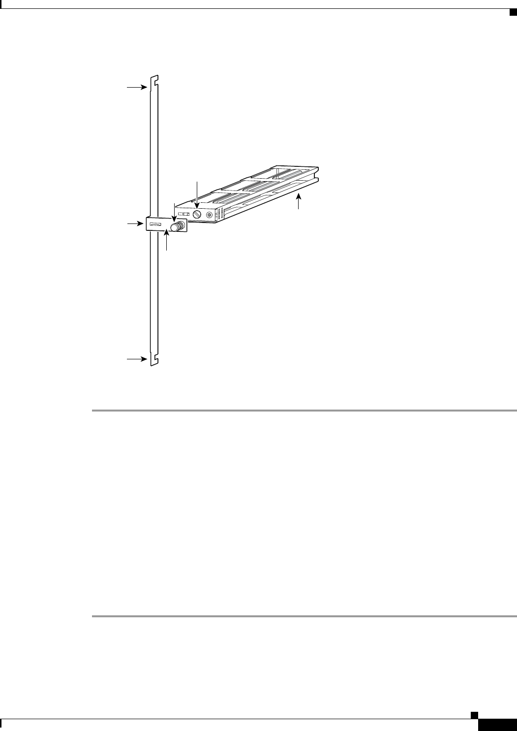
Figure 6-9 Guide Module Support Bracket
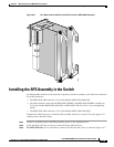
Step 6
Slide the center guide module carefully from the card cage.
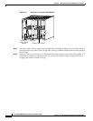
Step 7 Repeat Step 2 through Step 6 until you have removed the desired number of center guide modules.
Connecting the Back Cards to the APS Connector
Complete the following steps to connect the back cards to an APS connector. When the back cards are
installed in an APS connector, an APS assembly is formed. This procedure applies to all chasssis types,
using illustrations for the Cisco MGX 8830. For more information about other APS connector types,
refer to the following sections:
• MGX 8850, MGX 8850/B, and MGX 8880: “APS Assembly” section on page 1-28
• MGX 8950: “APS Assembly” section on page 1-41
• MGX 8830 and MGX 8830/B: “APS Assembly” section on page 1-52
For more information about APS line redundancy and compatibility information, see Chapter 4,
“Planning for Card Redundancy, Line Redundancy, and Bulk Distribution”
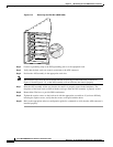
Step 1 Connect a grounding strap to the ESD grounding jack or to the equipment rack.
Step 2 Position the edge of the back card in the alignment slot of the APS connector and use the guide tabs on
the APS connector to align the holes on the back card with the pins on the APS connector.
(See Figure 6-10.)
48458
Center
guide
module
Faceplate
Support
bracket
Support
bracket
leg
Support
bracket
leg
Captive
screw
Jack
screw