


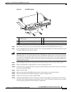

6-11
Cisco MGX 8800/8900 Series Hardware Installation Guide
Releases 2 - 5.2, Part Number OL-4545-01, Rev. H0, May 2006
Chapter 6 Maintaining the Cisco MGX Switch or Gateway
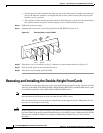
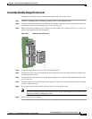
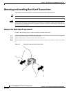
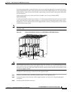
Removing and Installing the Back Cards
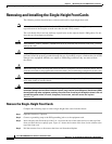
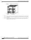
Step 5 Pull evenly on the two extractor levers to remove the back card from the card cage.
Step 6 Either replace the back card that you removed or cover the empty slot with a blank faceplate.
Note If a center guide module is removed from the rear and one double-height back card is installed,
install a double-height blank faceplate in the gap adjacent to the installed double-height card.
Two single-height blank faceplates cannot be used, because they require being screwed into the
center guide module that was just removed.
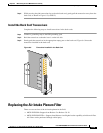
Install the Back Cards
Complete the following steps to install back cards in the chassis:
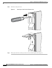
Step 1 Connect a grounding strap to the ESD grounding jack.
Step 2 Verify that there are no bent pins, bent dividers, or damaged connectors on the back cards (see the “Card
Installation and Replacement Suggestions” section on page 3-8).
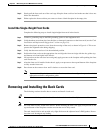
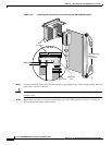
Step 3 Remove the plastic protective cover from the rear edge of the card, as shown in Figure 6-4. This cover
protects the alignment tabs during shipping.
Step 4 Verify that the two extractor levers on the back card are closed (flush with the vertical edge of the
back card).
Step 5 Position the back card over the appropriate slot guides and align the back card edge with the slot guides
(top and bottom or left and right) in the chassis.
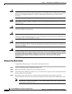
Step 6 Gently apply even pressure to the top and bottom of the faceplate while pushing the back card into the
slot.
Step 7 After the back card is installed in the chassis, apply even pressure to the top and bottom of the faceplate
to fully seat the back card.
Step 8 Use the flat-head or Phillips tip of the 3-in-1 tool to tighten the two captive screws on the back card
faceplate.
Note Tighten the top and bottom captive screws in increments to prevent misalignment of the card. Do not
overtighten the screws, but tighten them enough to secure the card.
Step 9 If you disconnected the cables or wires from the back cards, reconnect them.
Note If you are installing the back cards for the first time, see Appendix B, “Cable Specifications” for cabling
information.
If you are installing the back card for the first time, refer to the configuration procedures in the
appropriate software configuration guide.