


C-9
Cisco MGX 8800/8900 Series Hardware Installation Guide
Releases 2 - 5.2, Part Number OL-4545-01, Rev. H0, May 2006
Appendix
Bonding and Grounding the Cisco MGX System
Except for the AC power supply modules, every module in a rack-mount system uses the rack for
grounding. Therefore, the rack must connect to protective earth ground, and the equipment must be
secured to the rack so as to ensure good bonding.
A DC-powered node must have grounding conductors that connect at two separate locations:
• The grounding conductor provided with the supply source must connect to the correct terminal of
the power entry module (PEM).
• A grounding conductor must connect to an appropriate terminal on a rack or the chassis of a node.
For DC-powered systems, Cisco has designed the Cisco MGX 8800 and MGX8900 series switches to
connect to a non-isolated ground system. In contrast, routers and other LAN equipment often use an
isolated grounding scheme.
If properly wired together through an equalization connection as described in ITU-T recommendation
K.27, the isolated and non-isolated ground systems can form a mixed grounding system. The potential
between any points in the ground system—whether or not the ground system is mixed—must not exceed
2 percent of the referenced voltage (2 percent of 48 V is 960 millivolts).
Bonding and Grounding MGX 8800 or MGX 8900 Series Chassis in a Rack
To maintain proper grounding/ bonding connections when installing an MGX 8800 or MGX 8900 series
chassis in a rack, clean all paint from the surface of the rack rails that face to the unpainted surfaces of
the MGX mounting flanges and apply an anti-oxidant to the unpainted surfaces. Then install the chassis.
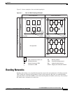
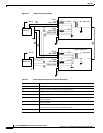
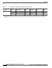
Wiring a Mixed Ground System with Redundant Supplies
A mixed ground system appears in Figure C-2. This figure shows safety and earth grounds and the
primary and redundant DC sources Battery A and Battery B. Individual ground conductors are labeled
Z1, Z2, Z3, Z4, and Z5. The Z represents the impedance of the ground conductor between a chassis, for
example, and a connection to the building’s ground system.
The numbers 1–4 represent building ground points and indicate that an impedance can exist between
different points in the ground system of the building. Each of these symbols indicates that a voltage drop
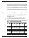
may result (but must not exceed 2 percent of the referenced voltage). See Table C-1 for a definition of
each Z1–Z5.