


6-21
Cisco MGX 8800/8900 Series Hardware Installation Guide
Releases 2 - 5.2, Part Number OL-4545-01, Rev. H0, May 2006
Chapter 6 Maintaining the Cisco MGX Switch or Gateway
Removing the Back Cards from an APS Assembly
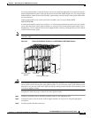
Removing the Back Cards from an APS Assembly
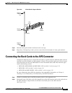
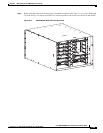
Complete the following steps to remove back cards from an APS assembly and to remove the APS
connector from the card compartment.
Caution Do not use a power screwdriver on captive screws.
Do not rock a card when removing it from a connector. Doing so can bend or damage the APS connector
pins.
Step 1 Connect a grounding strap to the ESD grounding jack or to the equipment rack.
To remove one of the back cards connected to the APS assembly:
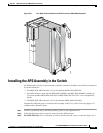
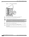
Step 2 Use the flat-head or Phillips tip of the 3-in-1 tool to loosen the two captive screws located on the top and
bottom of the back card faceplate.
Step 3 Pull each of the two extractor levers, located at the top and bottom of the faceplate, out to the horizontal
position.
Step 4 Pull evenly on the two extractor levers to remove the back card from the APS connector.
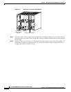
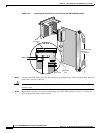
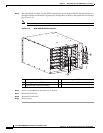
Step 5 Repeat 2 through Step 4 for the remaining back card in the APS connector. The APS connector will still
be connected to the second back card when it is removed and will come out of the card compartment
with the card.
Step 6 Carefully separate the second back card from the APS connector by pulling it out with a straight motion.
Step 7 Place the back cards and APS connector in antistatic bags or on an antistatic bench.
Step 8 Repeat through Step 4 for any remaining APS assemblies.
Replacing Processor Cards
With the availability of MGX Release 4.0.00, you might want to replace a PXM45 or PXM45/B
processor card with a PXM45/C processor cards. Or you might want to upgrade a PXM1E-4-155 card to
a PXM1E-8-155 card. Both of these procedures are described in the Cisco MGX 8800/8900 Series
Configuration Guide, Release 5.2. To find that manual online, go to www.cisco.com and search for the
part number.