


2-50
Cisco MGX 8800/8900 Series Hardware Installation Guide
Releases 2 - 5.2, Part Number OL-4545-01, Rev. H0, May 2006
Chapter 2 Illustrated Card List for MGX Switches and the MGX 8880 Media Gateway
Front Cards
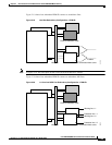
Note In Figure 2-20, the clock ports on the UI-S3 back cards must be Y-cabled.
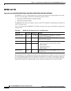
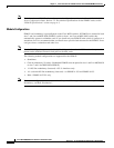
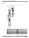
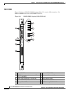
Figure 2-21 shows how a single PXM1E connects to redundant APS lines.
Figure 2-21 1:1 APS Line Redundancy Configuration—PXM1Es
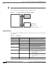
Faceplate Features
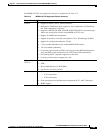
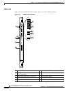
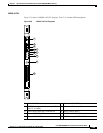
There are four models of the PXM1E (see Figure 2-22 through Figure 2-26). Table 2-23 describes LEDs
on the PXM1Es.
PXM1E front card OC-3c or OC-3c/DS3 combination back cards
Working line
80147
Midplane
Protection line
PXM-UI-S3/B back card
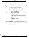
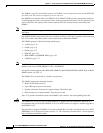
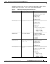
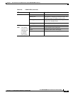
Table 2-23 PXM1E LEDs
LED Status Description
E1, E3, T1, or T3 Green The module is in E1, E3, T1, or T3 mode.
CR Blue A critical alarm is active.
MJ Red A major alarm is active.
MIN Yellow A minor alarm is active.
DC-A Green The first power supply is operating correctly.
Red The first power supply has failed.
DC-B Green The second power supply is operating correctly.
Red The second power supply has failed.
ACO Yellow An audible alarm is on.
Note Press the ACO button to turn the
audible alarm off.
HIST Green There is alarm history on the card.
Note Press the HIST button to clear the alarm
history.
ENET Flashing green Traffic is detected on the Ethernet interface.