


6-20
Cisco MGX 8800/8900 Series Hardware Installation Guide
Releases 2 - 5.2, Part Number OL-4545-01, Rev. H0, May 2006
Chapter 6 Maintaining the Cisco MGX Switch or Gateway
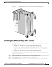
Installing the APS Assembly in the Switch
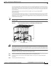
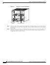
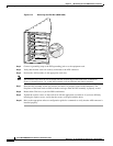
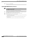
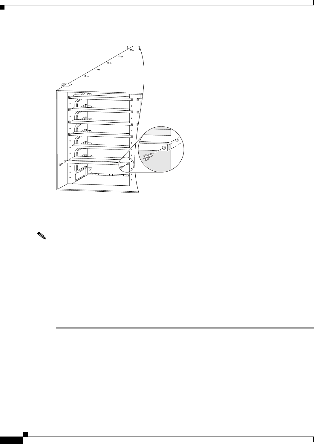
Figure 6-12 Removing the Filler Bar (MGX 8830)
Step 4 Connect a grounding strap to the ESD grounding jack or to the equipment rack.
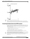
Step 5 Verify that the back cards are securely connected to the APS connector.
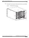
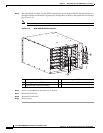
Step 6 Position the APS assembly in the appropriate card slots.
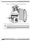
Note The extractor levers must be closed (flush with the vertical edge of the back cards, as shown in
Figure 6-10 and Figure 6-11), or the APS assembly will not slide into the chassis properly.
Step 7 Slide the APS assembly all the way into the slot until it is properly seated in the backplane. The
faceplates of the back cards are flush with the card cage when the APS assembly is properly seated.
Step 8 Reattach the filler bars, to provide EMI containment.
Step 9 Tighten the captive screws on the back cards with the appropriate screwdriver. If you have difficulty
inserting the captive screws, verify that the screws are aligned with the holes.
Step 10 Refer to the appropriate software configuration guide for commands to verify that the APS connector is
installed properly.
80168