


2-69
Cisco MGX 8800/8900 Series Hardware Installation Guide
Releases 2 - 5.2, Part Number OL-4545-01, Rev. H0, May 2006
Chapter 2 Illustrated Card List for MGX Switches and the MGX 8880 Media Gateway
Front Cards
• Bulk Distribution—MGX 8830, MGX 8850 (PXM45), and MGX 8850 (PXM1E)
For module configuration information, refer to Chapter 4, “Planning for Card Redundancy, Line
Redundancy, and Bulk Distribution”.
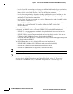
The following are card-level characteristics that apply to any SRM installation:
• No other service modules can be installed in the SRM slots because the slots do not have cell bus
connections. The SRM cards use a local bus to communicate with the PXM45 or PXM1E installed
in the same bay. Only SRM cards can be installed in slots:
–
15, 16, 31, and 32 for an MGX 8850 (PXM1E or PXM45) switch.
–
7 and 14 for an MGX 8830 switch.
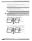
• On an MGX 8850 (PXM1E or PXM45) switch, the PXM45 or PXM1E in slot 7 controls the SRM
cards in slots 15 and 31. The PXM45 or PXM1E in slot 8 controls the redundant SRM cards in slots
16 and 32.
• On an MGX 8830, the PXM1E in slot 1 controls the SRM card in slot 7, and the PXM1E in slot 2
controls the redundant SRM card in slot 8.
• Both SRM cards in a pair must be the same model. You can have two SRM-3T3/Cs or two SRME
cards. However, you cannot mix an SRME with an SRM-3T3/C.
• The PXM45 cards support only the SRME card.
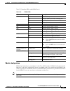
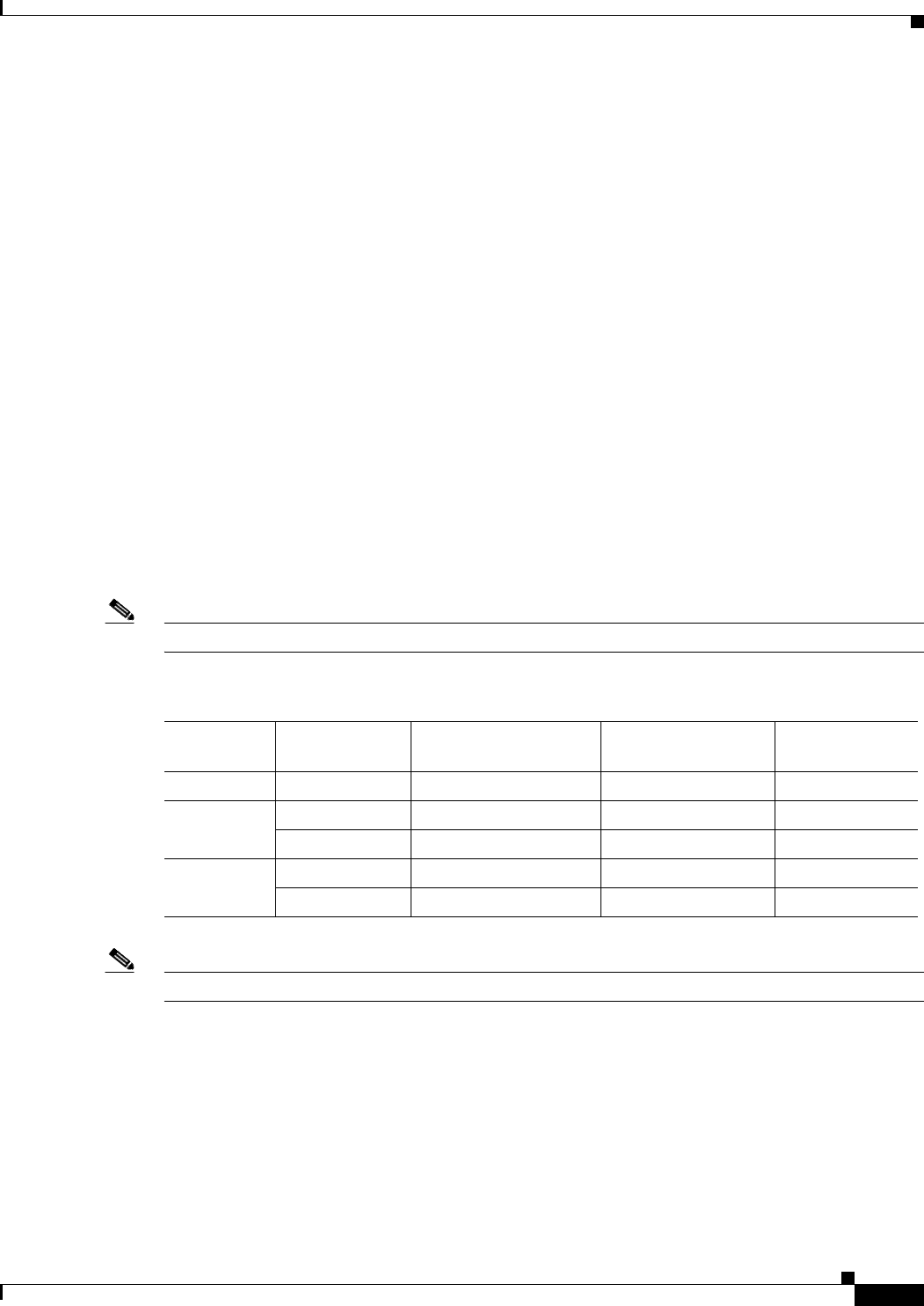
When the SRM is combined with a back card, a card set is created. Table 2-29 provides information
about each SRM card, interface, and corresponding back card.
Note Back cards are optional for BERT and 1:N card set redundancy.
Note For technical specifications for the SRM cards, see the “SRM Specifications” section on page A-8.
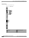
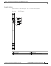
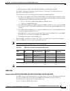
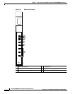
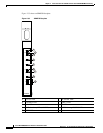
SRM-3T3/C
Supported models: MGX 8850 (PXM1E/PXM45), MGX 8850/B (PXM1E/PXM45), MGX 8830, MGX 8830/B
The SRM-3T3/C provides bulk distribution (on T1 lines only), 1:N card set redundancy for the T1 and
E1 service modules, and bit error rate testing (BERT). Bulk distribution manages traffic over
T3 interfaces and is supported for T1 interface speeds only.
Figure 2-31 shows an SRM-3T3/C faceplate.
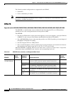
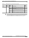
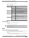
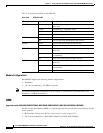
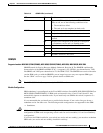
Table 2-29 SRM Cards, Interfaces, and Supported Back Cards
SRM
Supported Back
Card Interface Connection
Types of Lines
Supported
Number of Lines
Supported
SRM-3T3/C BNC-3T3/C Channelized T3 T3 3
SRME/B SMFIR-1-155 Channelized T3 T3 3
STM1-EL-1 Channelized 155 Mbps STM1 SDH 1
SRME SMFIR-1-155 Channelized 155 Mbps OC-3c/STS SONET 1
STM1-EL-1 Channelized 155 Mbps STM1 SDH 1