


5-78
Cisco MGX 8800/8900 Series Hardware Installation Guide
Releases 2 - 5.2, Part Number OL-4545-01, Rev. H0, May 2006
Chapter 5 Installing the Cisco MGX Switch or Gateway
Installing the MGX 8950 Switch
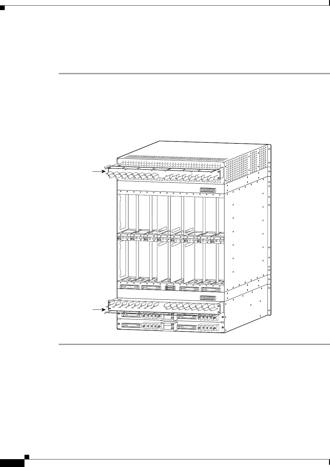
Install the Cable Management Assembly
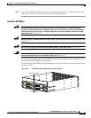
The cable management assembly consists of two identical, horizontal cable managers, two mounting
brackets, and screws. Complete the following steps to install the cable management assembly:
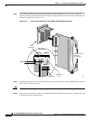
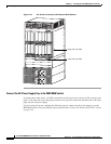
Step 1 Use the provided No. 10-32 screws and the appropriate screwdriver to attach the two mounting brackets
to the right and left sides of the rear of the air intake and exhaust plenums.
Step 2 Use the provided No. 10-32 screws and the appropriate screwdriver to install the cable managers on the
mounting brackets. The cable guides on the upper cable manager must be on the bottom. The cable
guides on the lower cable manager must be on the top. See Figure 5-45.
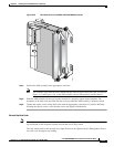
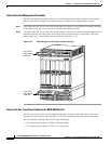
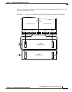
Figure 5-45 Cable Management Assembly at Back of System
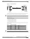
Connect the Fan Tray Power Cables to the MGX 8950 Switch
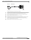
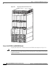
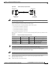
The fan trays receive power from the backplane through a fan power cable. See Figure 5-46 for an
illustration of the fan power cable and Figure 5-47 for an illustration of the fan power connections.
You will need the following cables for fan cable installation:
• Cisco Systems part number 72-2083-xx (46-inch cable)
• Cisco Systems part number 72-2565-xx (12-inch cable)
66049
Upper cable
management
assembly
Lower cable
management
assembly